B1302, B1303
Symptom: TCS OFF lamp on, TCS symptom inoperative
Position sensor, TCS throttle butterfly, no continuity/short circuit

Fault symptom
TCS OFF lamp on, TCS symptom inoperative
Condition
For trouble code B1302:
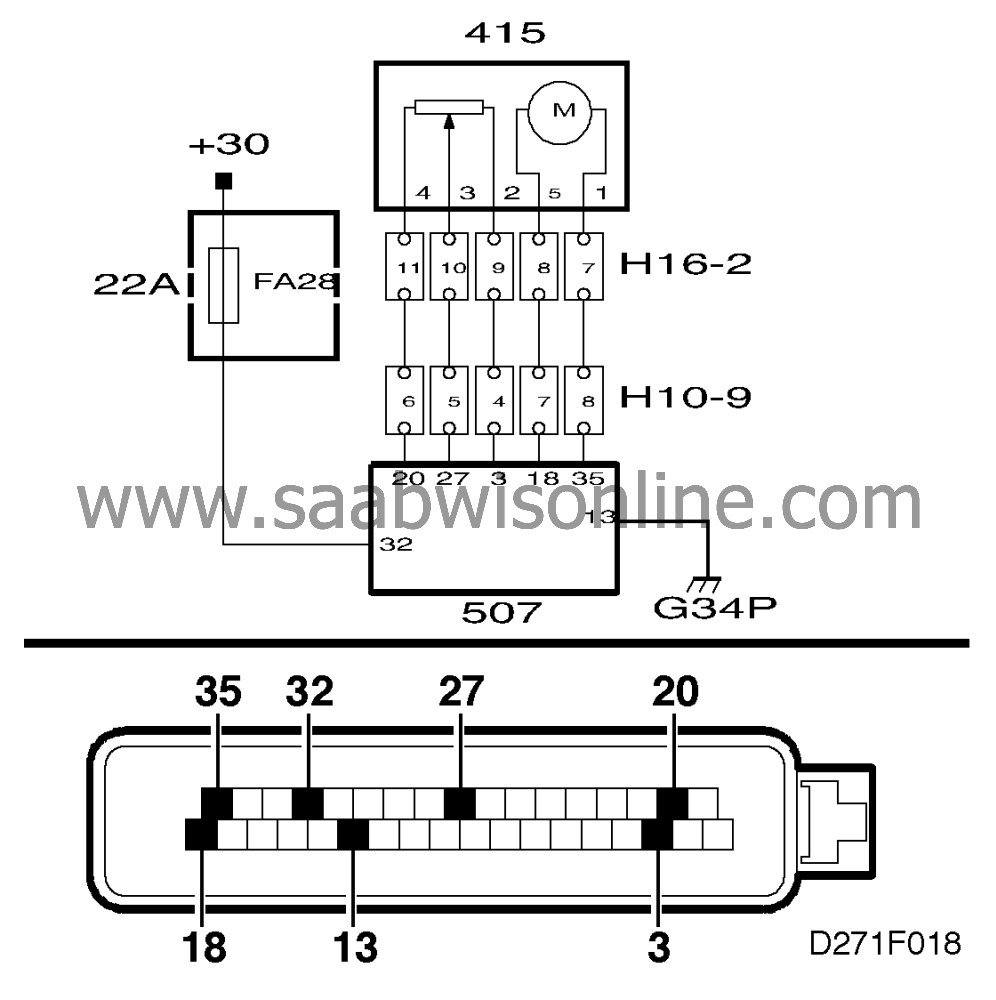
Control module output pin 3
shorted to ground or no continuity. Alternatively, control module input pin 27 shorted to
ground.
For trouble code B1303:
Control module output pin 20
shorted to B+ or no continuity. Alternatively, control module input pin 27 shorted to B+.
|
Note
|
|
B1302 and B1303 can be generated in connection with fault diagnosis when wiring to
the throttle body is disconnected and the ignition switch is turned to the Drive position.
|
Diagnostic procedure
|
1.
|
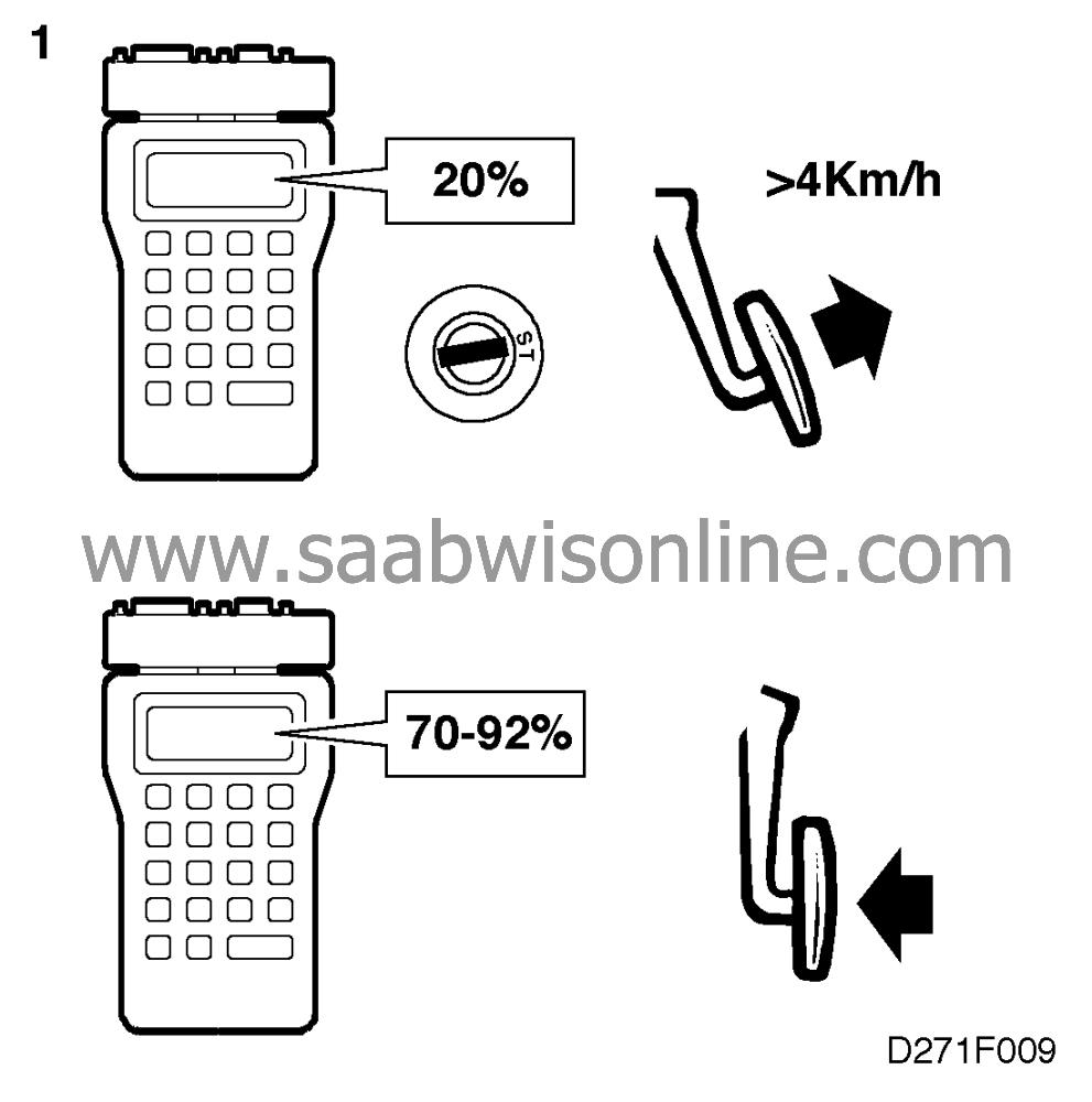
Connect an ISAT and
select "TCS THROTTLE POS" in the "OBTAIN READINGS" menu. Drive the car at >4
km/h. On releasing the accelerator the ISAT should show a reading of about 20%%. This should
then successively rise to 70-92%%at full throttle. (Note that the TCS throttle opens fully at
speeds <4 km/h.) If the readings are correct, clear the trouble code, drive the car on the
road and check whether the trouble code is generated afresh. If the readings are incorrect or if
the trouble code is generated afresh, proceed with point 2.
|
|
2.
|
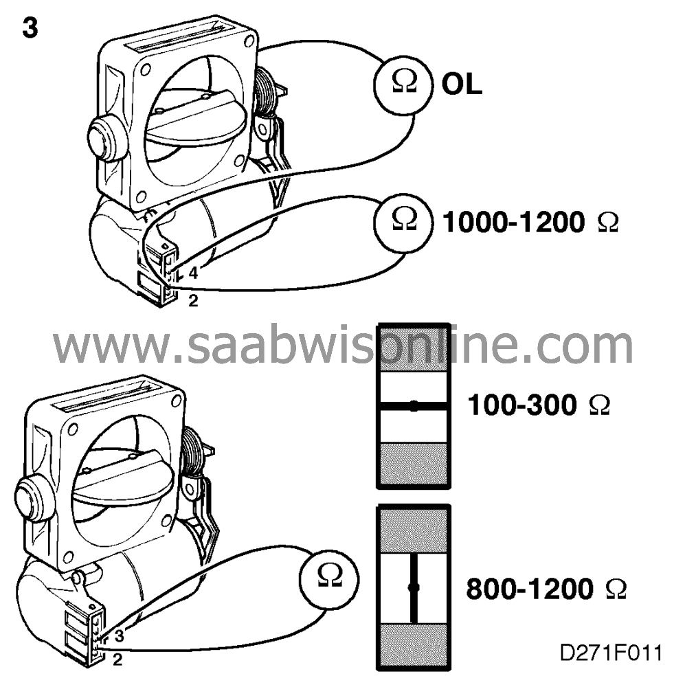
Switch off the ignition. Unplug connector H16-2 and measure the
resistance in the TCS throttle position sensor across pins 9 and 11 of the female
connector. The correct resistance is approx. 1000-1200 ohms. Also measure the resistance
across pins 9 and 10 of the female connector while slowly closing the throttle butterfly by
hand. The resistance should now rise smoothly from about 100-300 ohms to about 800-1200
ohms.


Also check that the resistance across pin 9 and a good ground is infinite
(OL).
If the resistance is OK, the fault lies between connector H16-2 and the control module.
Continue with point 4.
If it is not, the fault lies between connector H16-2 and the throttle body or in the throttle
body. Proceed to point 3.
|
|
3.
|
Remove the TCS throttle body.
Carry out checking as described in point 2 above, directly on throttle body pins 2, 3 and
4.
If the measurements produce correct readings, remedy the defective wiring between
the throttle body and connector H16- 2.
Should the measurements produce incorrect readings, on the other hand, fit a
replacement TCS throttle body.

|
|
4.
|
Turn the ignition switch to the drive position. Measure the voltage across
pin 9 of the male connector (H16-2) and B negative (-).

The correct voltage is about 5 V.
Also check that pin 11 of the male connector is correctly grounded by measuring the
voltage to B positive (+).
The correct voltage is battery +.
If the readings are correct, the supply from control module output pins 3 and 20
is correct and the fault lies between pin 27 of the control module and pin 10 of the male
connector (H16-2). Continue with point 5.
If the readings are incorrect, the fault lies between pin 20 of the control module and pin
11 of the male connector or between pin 3 of the control module and pin 9 of the male
connector. Proceed to point 6.

|
|
5.
|
Switch off the ignition.


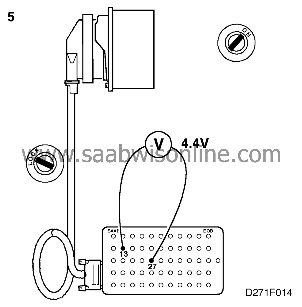
Remove the right-hand front seat, withdraw the TCS control module and plug in a BOB.
With the ignition switch in the drive position, check the cable for the input from the TCS
throttle butterfly's position sensor by measuring the voltage across pins 27 and 13 of
the TCS control module.
The correct voltage is about 4.4 V.
If this is not obtained, remedy the cable between pin 27 of the control module and pin
10 of the male connector (H16-2).
|
|
6.
|
Switch off the ignition.

Remove the right-hand front seat, withdraw the TCS control module and plug the BOB
into the control module connector (control module disconnected).
Check the cable between pin 3 of the control module and pin 9 of the male connector
(H16-2) and also the cable between pin 20 of the control module and pin 11 of the male
connector for continuity/shorting.
Remedy any defective wiring.
Plug in connector H16-2, connect the control module and turn the
ignition switch to the Drive position. Check that the control module is correctly grounded on pin
20 by measuring the voltage across pins 20 and 32.
Correct voltage is battery +.
Also check that there is a voltage of about 5 V on pin 3 of the control module by
measuring the voltage across pins 3 and 13.

|
|
7.
|
Clear the code diagnostic trouble code. Start the car and drive it on test
to check whether the diagnostic trouble code recurs. If it does, see "Before replacing a control
module" for further measures.

|


