P0327
Symptom: The car runs on basic boost pressure only, continuous ignition retard.
Knock sensor

Symptom of fault
The car runs on basic boost pressure only, continuous ignition retard.
|
Note
|
|
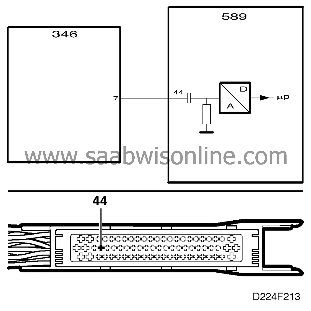
The Saab Trionic system does not have a conventional knock sensor. The signal
comes from the ignition discharge module.
|
Conditions
|
•
|
No knock signal for 10 seconds.
|
Diagnostic help
A knock signal reading can be obtained using an ISAT scan tool.
|
-
|
Select
"READ FUNCTIONS".
|
The ISAT scan tool should show a reading of between 0 and 2.55 V, depending
on the level of the knock signal.
At idling speed the ISAT scan tool should show a reading of 0.06-0.16 V. If the throttle is
opened suddenly, the ISAT scan tool could show a reading of 0.06-2.55 V.
In the event of a break in the signal lead connected to pin 44 of the control module, a
reading of 0.06-0.08 V will normally be obtained whatever the throttle opening.
Checking the wiring. Intermittent faults may occur as a result of occasional short circuits
and breaks in the wiring. Jiggle the leads and in-line connectors at several places and in
different directions to reveal faults in the wiring harness. Observe the multimeter, ISAT scan
tool or test lamp while carrying out this check.
Diagnostic procedure
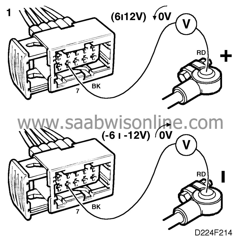
1. Check the electrical interface

|
-
|
Ignition switch in ON
position.
|
|
-
|
Unplug the ignition discharge
module's 10-pin connector.
|
|
-
|
Connect a multimeter, set for d.c.
voltage, to
|
|
|
•
|
Connector pin 7 and battery
positive (B+)
|
|
|
•
|
Connector pin 7 and battery negative (B-)
The multimeter should be connected alternately to battery positive (B+) and negative (B-
).
|
When connected to battery positive (B+), the meter should indicate a positive
voltage (about 6-12 V) which rapidly drops to 0 V.
When connected to battery negative (B-), the meter should indicate a negative voltage
(about -6 to -12 V) which rapidly rises to 0 V.
Are the readings obtained OK?
Continue with point 3.
Continue with point 2.
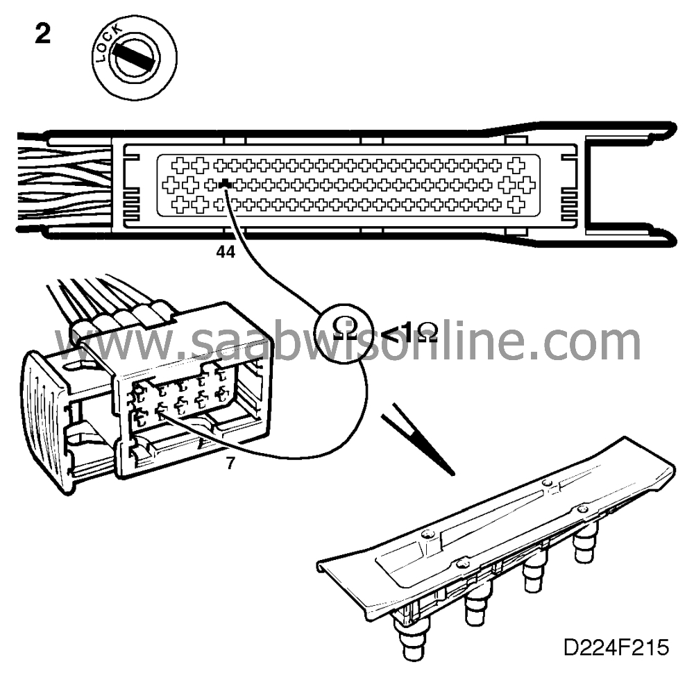
2. Check the knock signal's
lead

|
-
|
Check the continuity of the lead
between pin 7 of the ignition discharge module and pin 44 of the control
module.
|
|
-
|
Check the lead for open circuit and
shorting.
|
Are the resistance readings OK?
Continue with point 3.
Rectify the fault and proceed to point 3.
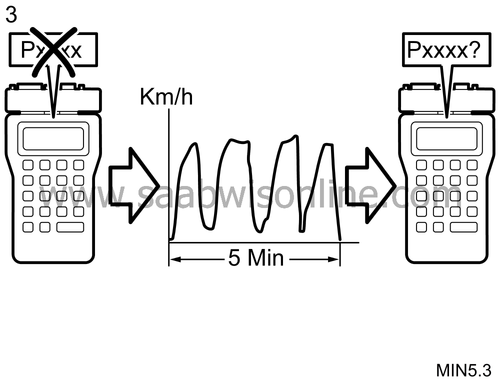
3. Final check

|
-
|
Clear the diagnostic trouble
code.
|
|
-
|
Implementation of driving cycle:
Drive the car at varying engine loads and rpm for 5 minutes.
|
|
-
|
Evaluation of driving cycle: Check
whether the diagnostic trouble code has recurred.
|
Has the diagnostic trouble code recurred?
Try fitting a replacement ignition discharge module and, after a repetition of the
driving cycle, check whether the diagnostic trouble code is generated afresh.
The remedial measure taken was correct.
Has the diagnostic trouble code been generated afresh after changing the ignition
discharge module?
Refit the original ignition discharge module and then continue as described on
 .
.
Scrap the original ignition discharge module. The remedial measure taken was
correct.


 .
.


