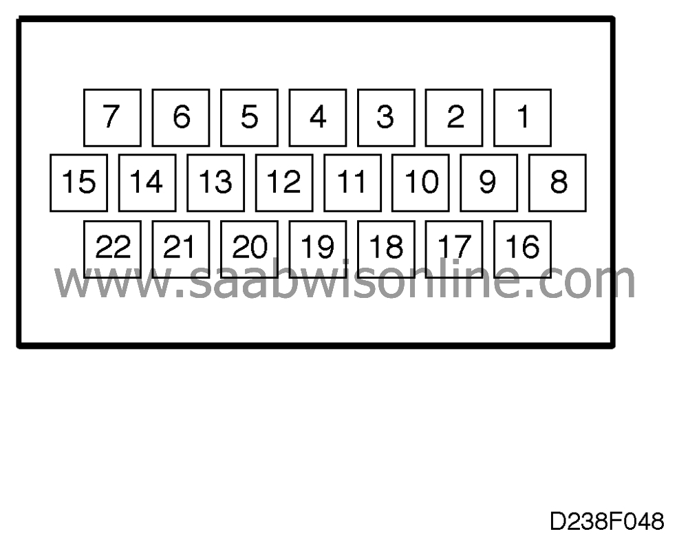
Test readings, control moduleconnections
| Test readings, control module connections |
| Remember: |
| • |
Unless otherwise stated, all
voltage measurements should be carried out with all components connected and with the
ignition switch in the Drive position.
|
|
| • |
Readings should be taken with a Breakout box (BOB) connected between the
SID unit and its connector.
|
|
| • |
Several voltage levels should be regarded as guiding values. Use your common
sense when judging whether a particular reading is correct or not.
|
|
| • |
If any reading is not OK, consult the wiring diagram to trace the leads,
connectors or components which ought to be checked more thoroughly.
|
|
|
Pin
|
Colour
|
Component/function
|
In/Out
|
Test
conditions
|
Test
reading
|
Across X
Y
|
|
1
|
GY/WH
|
Washer fluid level
sensor
|
In
|
Washer fluid present (closed) Washer
fluid not present (open)
|
0 V 12 V
|
1-20
|
|
2
|
|
Not used
|
|
|
|
|
|
3
|
BK/GN
|
Coolant level sensor
|
In
|
Coolant present (closed) Coolant not
present (open)
|
0 V 12 V
|
3-20
|
|
4
|
BN
|
Filament monitor, front
lamps
|
In
|
OFF ON
|
12 V 0 V
|
4-20
|
|
5
|
PK
|
TSAS
|
In
|
|
Variable voltage 0-12 V
|
5-20
|
|
6
|
RD
|
SENSONIC
|
In
|
Ignition ON Activate SID with Scan Tool
- No fault - Overheated clutch
|
9-10 V LP HIp LOp 5-6 V LP HIp
LOp
|
6-20
|
|
7
|
|
Not used
|
|
|
|
|
|
8
|
BN/WH
|
ICE data
|
In
|
No message
|
about 8 V
|
8-20
|
|
9
|
YE/GY
|
Ignition +15
|
In
|
Ignition on
|
< 0.5 V
|
B+ -9
|
|
10
|
|
Not used
|
|
|
|
|
|
11
|
|
Not used
|
|
|
|
|
|
12
|
BU/GY
|
Bulb failure in main instrument display
panel 1
|
Out
|
Lamp lit Lamp out
|
0 V 12 V
|
15-12
|
|
13
|
RD/WH
|
Washer fluid bulb in main instrument
display panel 1
|
Out
|
Lamp lit Lamp out
|
0 V 12 V
|
13-15
|
|
14
|
|
Not used
|
|
|
|
|
|
15
|
RD/WH
|
Ignition +30
|
In
|
|
< 0.5 V
|
B+ -15
|
|
16
|
BN/OG
|
Bus +
|
In/Out
|
Ignition on
|
2.5 V
|
16-20
|
|
17
|
BU/OG
|
Bus -
|
In/Out
|
Ignition on
|
2.5 V
|
17-20
|
|
18
|
BU/GN
|
Outside temperature sensor
ground
|
In
|
|
12 V
|
15-18
|
|
19
|
YE/GN
|
Outside temperature
sensor
|
In
|
Ignition on
|
about 1.5-2.5 V at 20
°C
|
19-20
|
|
20
|
BK
|
Signal ground
|
In
|
Ignition on
|
< 0.1 V
|
20-batt-
|
|
21
|
|
Not used
|
|
|
|
|
|
22
|
VT/WH
|
Rheostat
|
In
|
Rheostat MIN @ HALF MIN
MAX
|
about 2 V about 12 V
|
22-20
|


