Fault diagnosis, charging indicator lamp (MIU2)
|
|
Fault diagnosis, charging indicator lamp (MIU
2)
|
Fault symptoms
The lamp does not light up when the ignition switch is turned to the Drive
position.
Diagnostic procedure


|
1.
|
Check whether the brake fluid warning lamp
lights up when the ignition switch is turned to the Drive position.
If the lamp lights up, continue with point 2.
If it does not light up, proceed to point 3.
|
|
2.
|
Change the bulb.
If the lamp still fails to light up when activated, check that the new bulb is OK by fitting it
in place of another bulb in the main instrument display panel that does light up.
If the bulb is OK, the fault is probably in the intermediate part of the main instrument
display panel which will then have to be changed.
|
|
3.
|
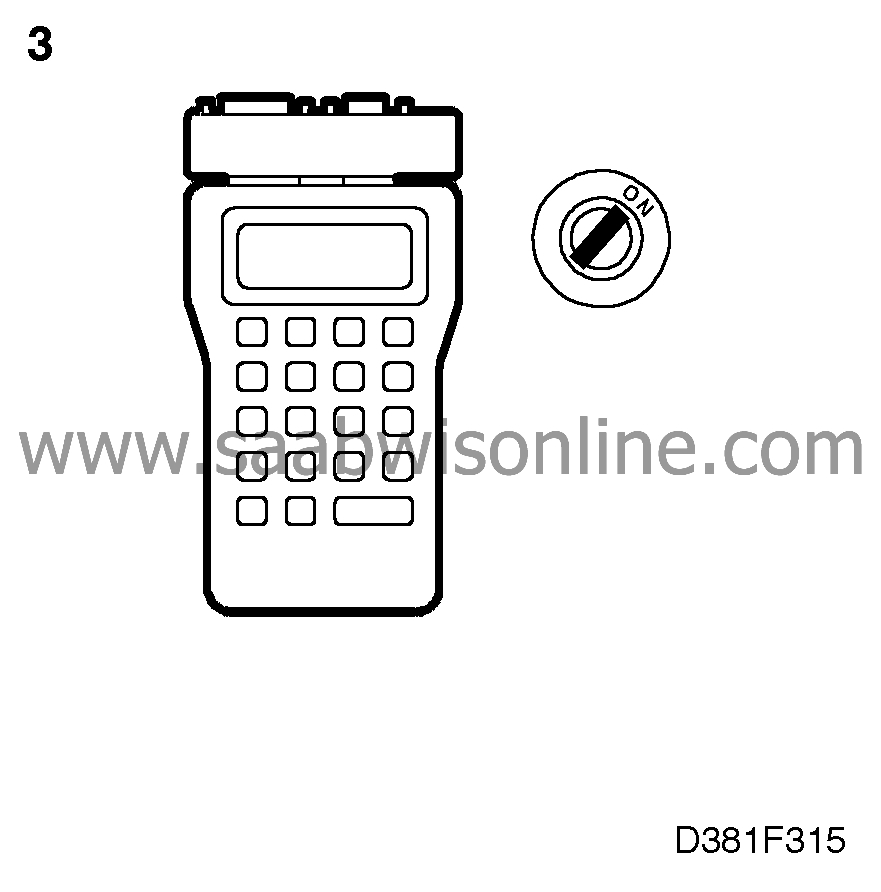
Check the input signal to the main instrument display panel by connecting an
ISAT Scan Tool and then selecting "READ VALUES" followed by "WARNING INPUTS" and
"CHARGE WARN".


With the engine switched off and the ignition switched on, the Scan Tool's display
should read "CHARGE WARN ON" if the charging indicator lamp is in proper working
order.
If it is in proper working order, both bulbs (charging lamp and brake fluid level) could be
faulty. Continue with point 4.
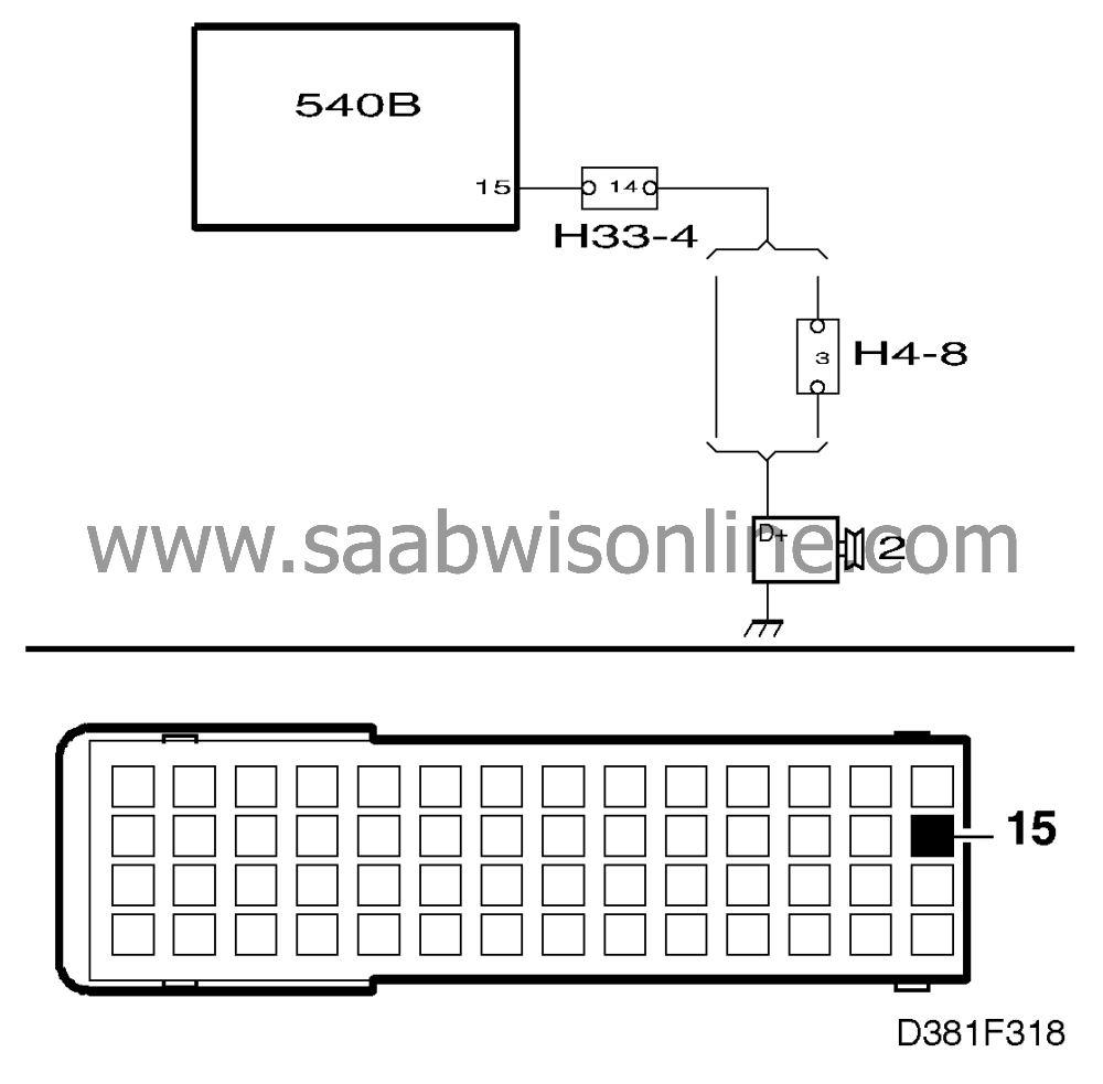
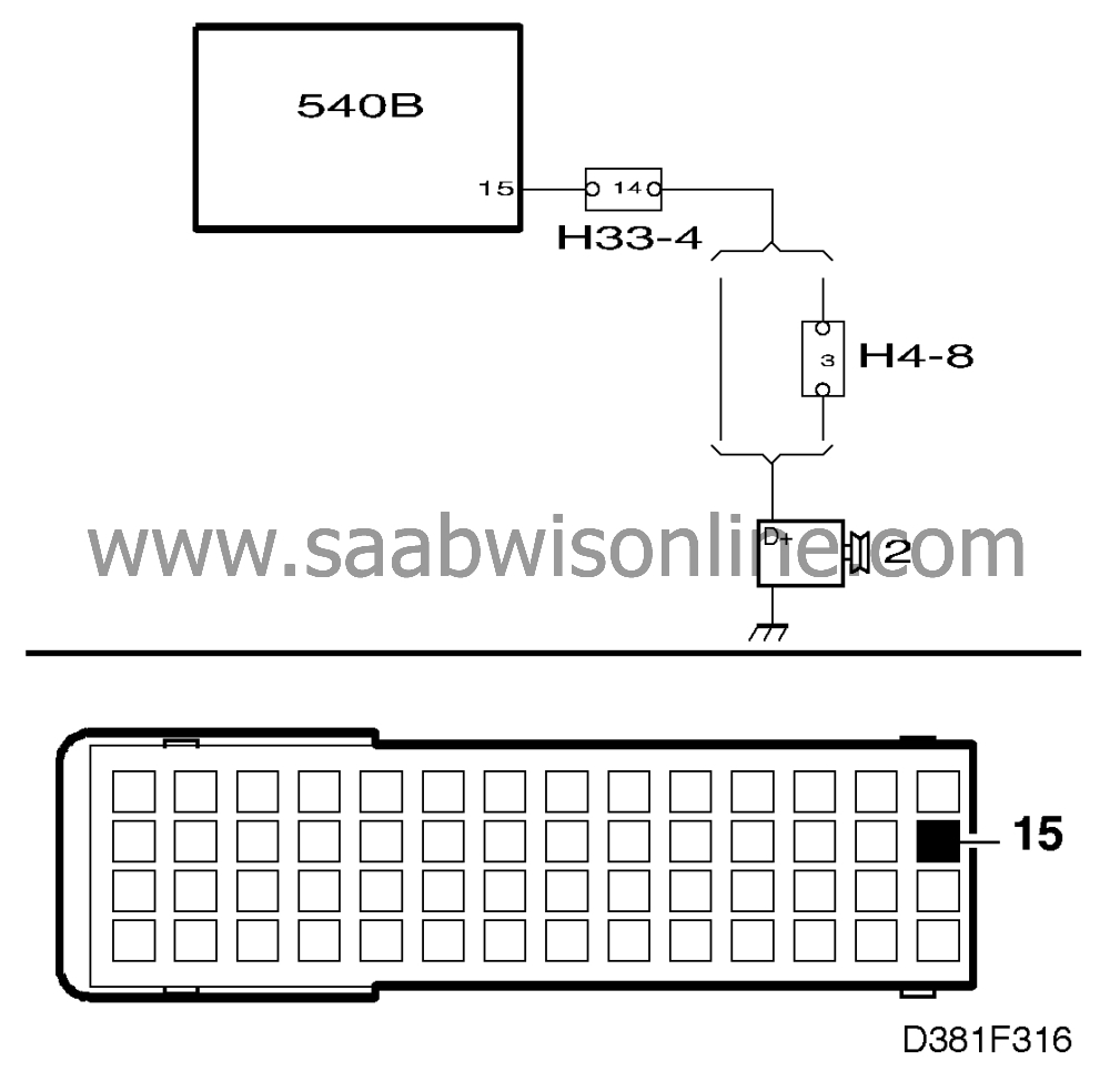
If the display reads "CHARGE WARN OFF" (battery voltage on pin 15), there is
probably an open circuit in the wiring between the main instrument display panel and the
generator. Continue with point 5.
|
|
4.
|
Check by changing both bulbs.
If the new bulbs still do not light up when activated, there could be an internal fault in the
main instrument display panel. Remove the main instrument display panel's rear
section complete with processor card and check that all leads between the processor card
and the intermediate part are securely located. If any lead has worked loose or is broken,
continue on
 .
.
If the connections are OK, the fault is probably in the intermediate part with bulbs and
indicating instruments. Continue on
 .
.
|
|
5.
|
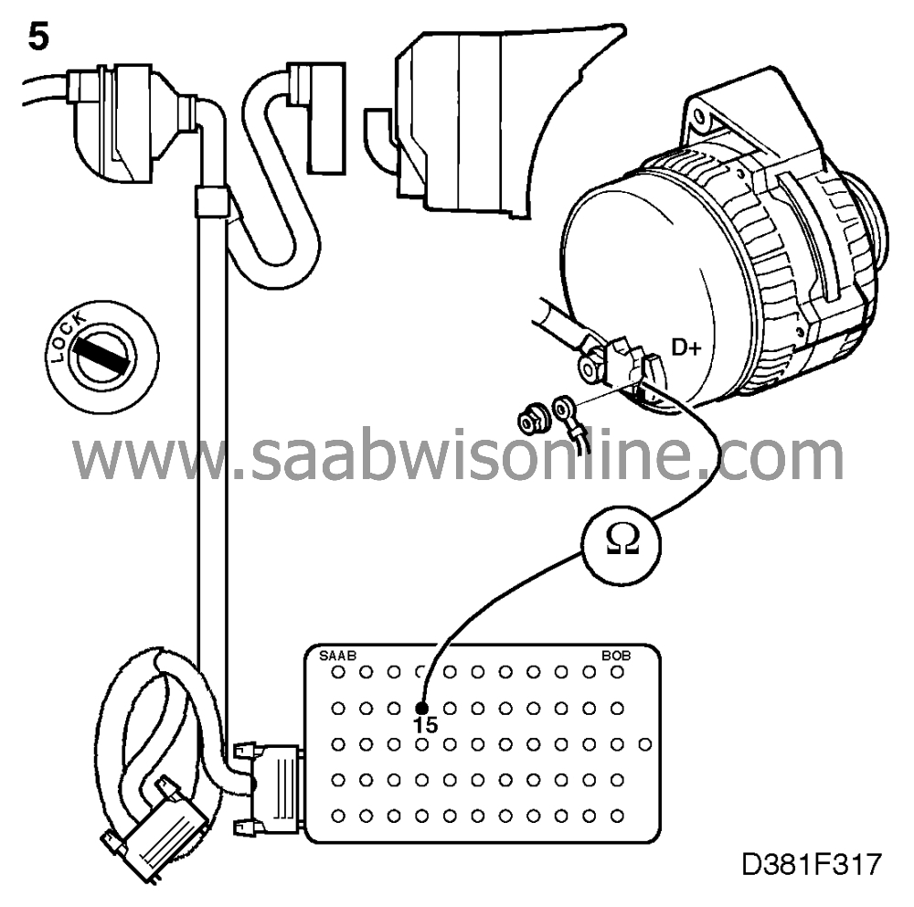
Check the wiring by connecting a BOB to the 56-pin connector behind the main
instrument display panel (which should not be connected).

Take a reading across pin 15 on the BOB and terminal D+ on the generator to check for
an open circuit.
If there is an open circuit, investigate the cause and take appropriate
action.
|


