Fault diagnosis, indicator and warning lamps(MIU 1)
|
|
Fault diagnosis, indicator and warning lamps
(MIU 1)
|
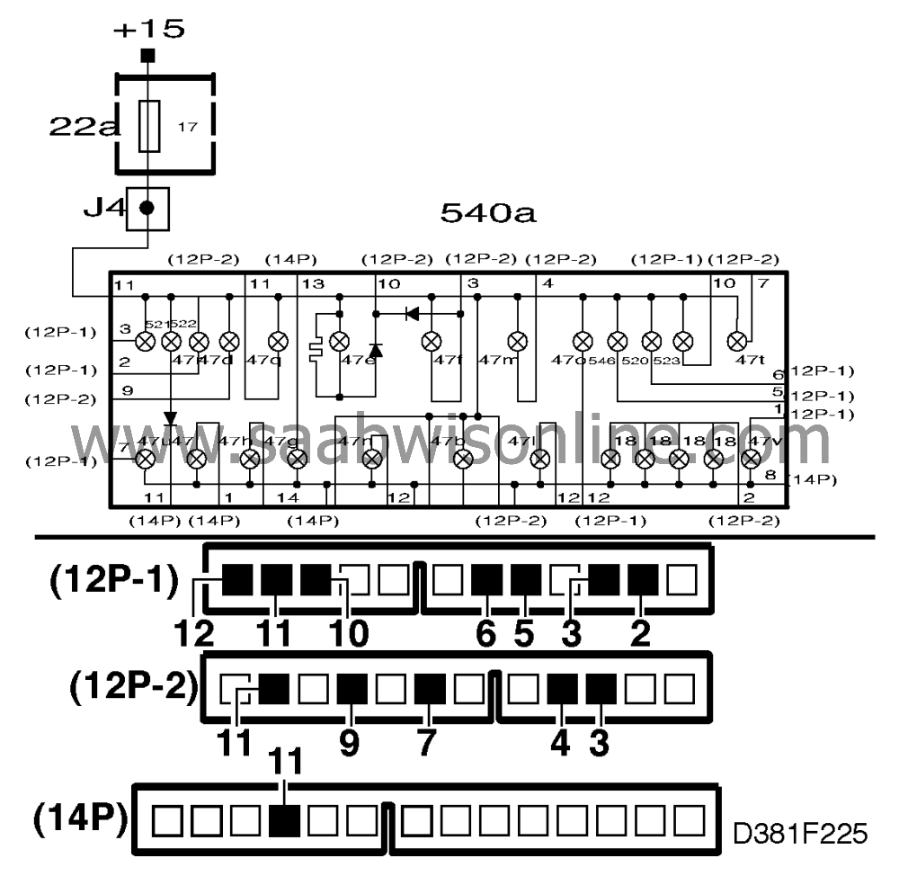
Includes:
|
•
|
SPORT indicator lamp pin 5 (white 12p)
|
|
•
|
WINTER indicator lamp pin 6 (white 12p)
|
|
•
|
CHECK ENGINE warning lamp (MIL) pin 12 (white 12p)
|
|
•
|
CHECK GEARBOX warning lamp pin 10 (white 12p)
|
|
•
|
"Open door" warning lamp, pin 11 (14p)
|
|
•
|
Oil pressure warning lamp pin 9 (black 12p)
|
|
•
|
Brake fluid level warning lamp pin 3 (black 12p)
|
|
•
|
Handbrake warning lamp pin 4 (black 12p)
|
|
•
|
ABS (ANTI LOCK) warning lamp pin 11 (black 12p)
|
|
•
|
SRS warning lamp, pin 7 (black 12-p)
|
|
•
|
"Faulty bulb" warning lamp pin 3 (white 12p)
|
|
•
|
Washer fluid level warning lamp pin 2 (white 12p)
|
The above indicator and warning lamps are supplied with battery voltage from
the main instrument display panel (+15 supply) and grounded in their systems outside the
main instrument display panel.
Fault symptoms
If none of the above lamps work and the engine cannot be started, fuse 17 has probably
blown.
Diagnostic procedure
|
1.
|
Check whether fuse 17 is intact and
supplied with current.
|
|
2.
|
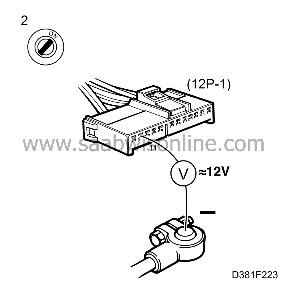
Check that battery voltage is present on pin 11 of the main instrument display
panel by taking a reading across pin 11 (white 12p) of the connector and a good grounding
point.
|
|
3.
|
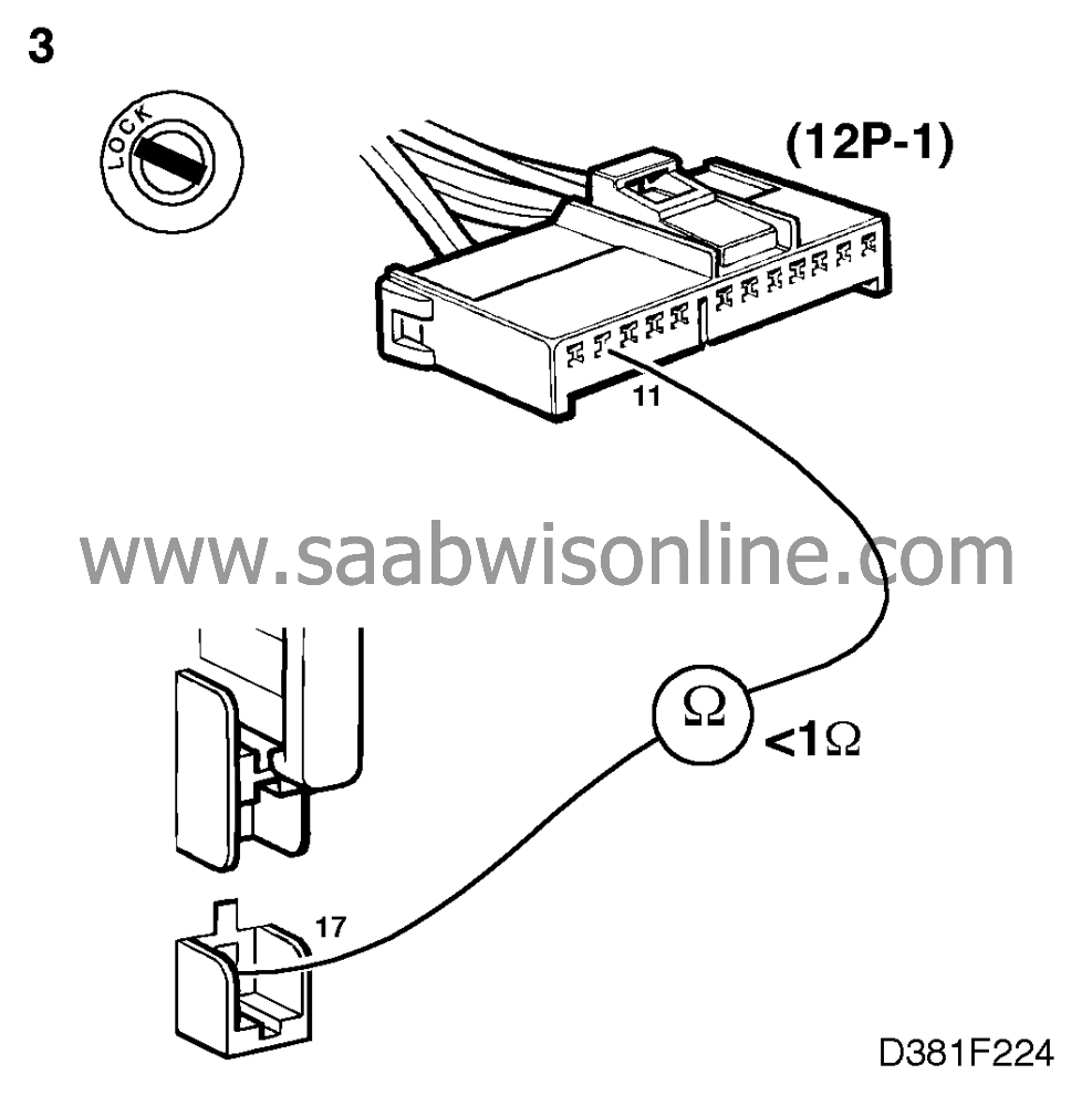
Check the wiring harness for continuity/shorting by taking a resistance reading
across the output of the fuse and pin 11 (white 12p) of the main instrument display panel.
|
Fault symptoms
Indicator or warning lamp fails to light up when activated.
Diagnostic procedure
|
1.
|
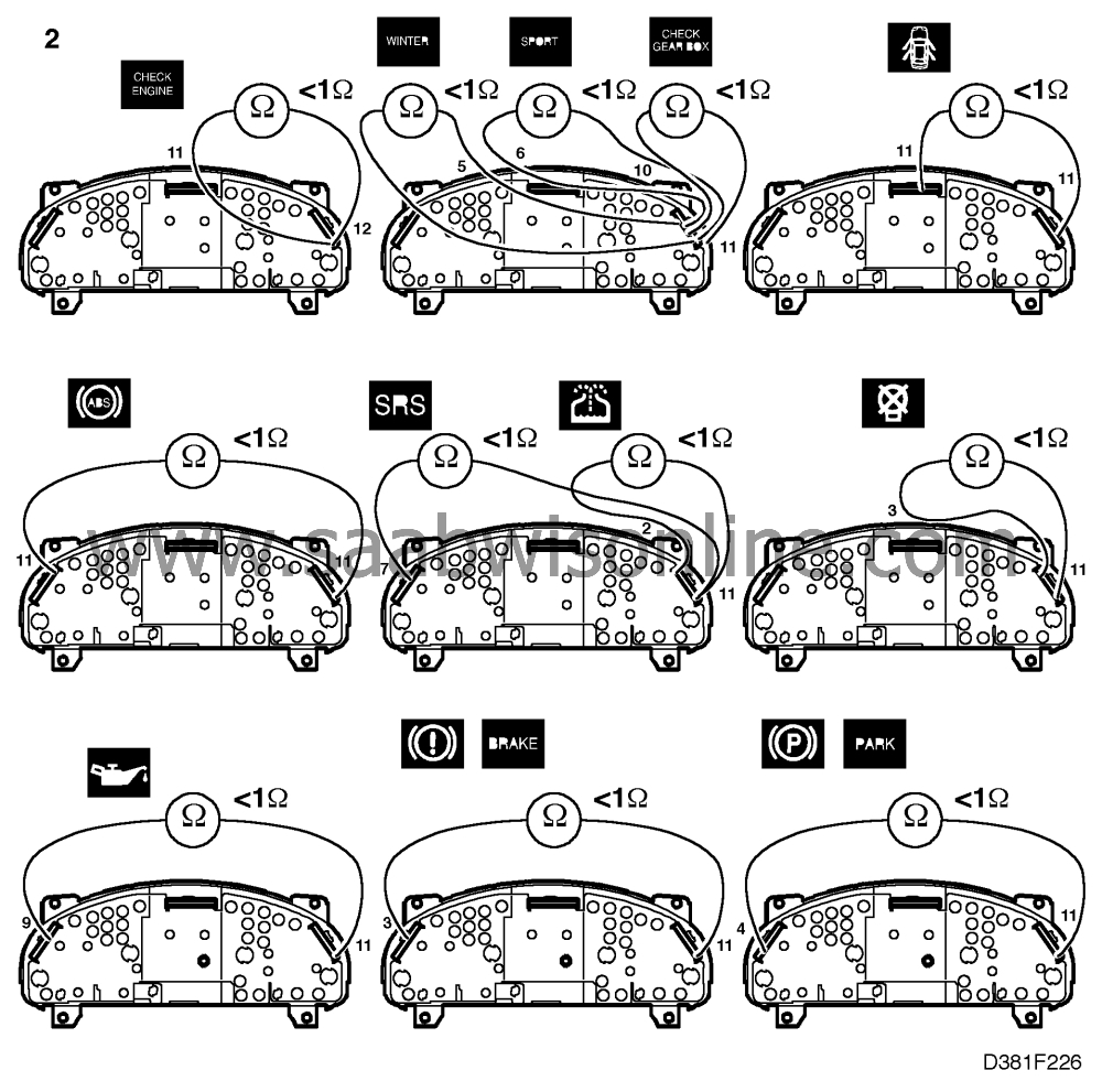
If the indicator or warning lamp fails to light up
when it should, the bulb is probably faulty and must be changed. If the replacement bulb still
fails to light up when activated, check that the new bulb is OK by fitting it in place of another
bulb in the main instrument display panel that does light up.
|
|
2.
|
Check the conductive foil on the rear of the main instrument display panel for an
open circuit between the bulb's ground connection and the foil's corresponding
connection to the connector.
|
|
3.
|
If there is an open circuit in the conductive foil, change the foil.
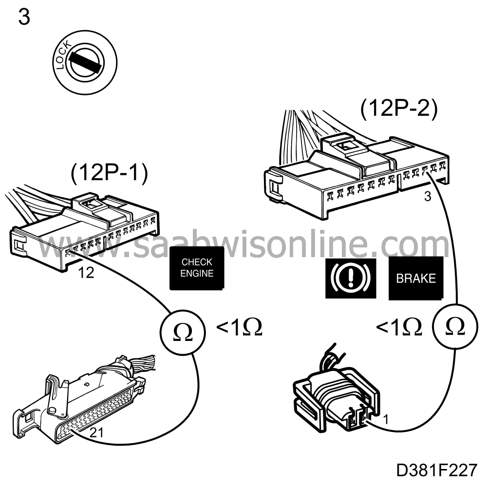
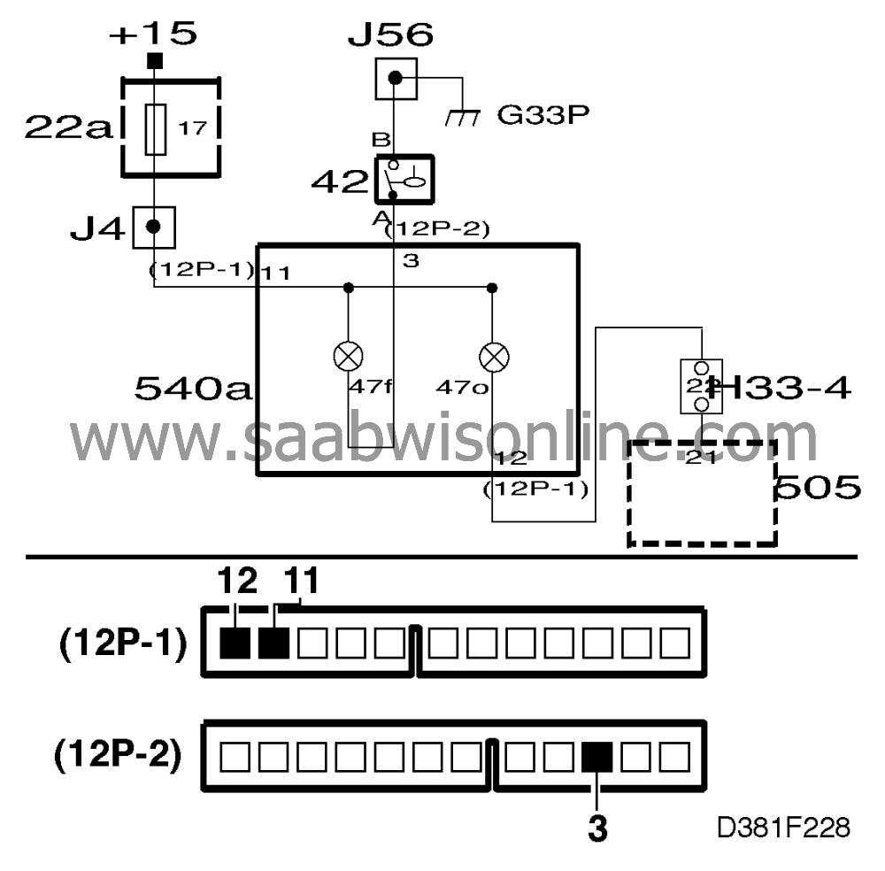
If the conductive foil is intact, there is probably an open circuit in the wiring to the
lamp's sensor. Check the wiring for an open circuit between the main instrument
display panel and the bulb's sensor by measuring the resistance.
Lamp
|
Main instrument display
panel pin
|
Sensor
pin
|
SPORT
|
5 (12p-1)
|
24
|
WINTER
|
6 (12p-1)
|
7
|
CHECK ENGINE (MIL)
|
12 (12p-1)
|
8 (M2.10.2) 32 (TRIONIC)
|
CHECK GEARBOX
|
10 (12p-1)
|
6
|
"Door open"
|
10 (11p)
|
31
|
Oil pressure
|
9 (12p-2)
|
1
|
Brake fluid
|
3 (12p-2)
|
1
|
Handbrake
|
4 (12p-2)
|
1
|
ABS
|
11 (12p-2)
|
1
|
SRS
|
7 (12p-2)
|
1
|
"Faulty bulb"
|
3 (12p-1)
|
12
|
Washer fluid
|
25 (12p-1)
|
13
|
|
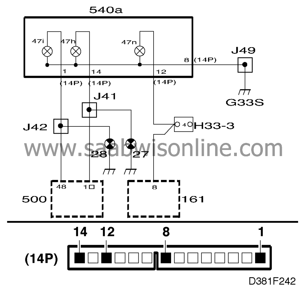
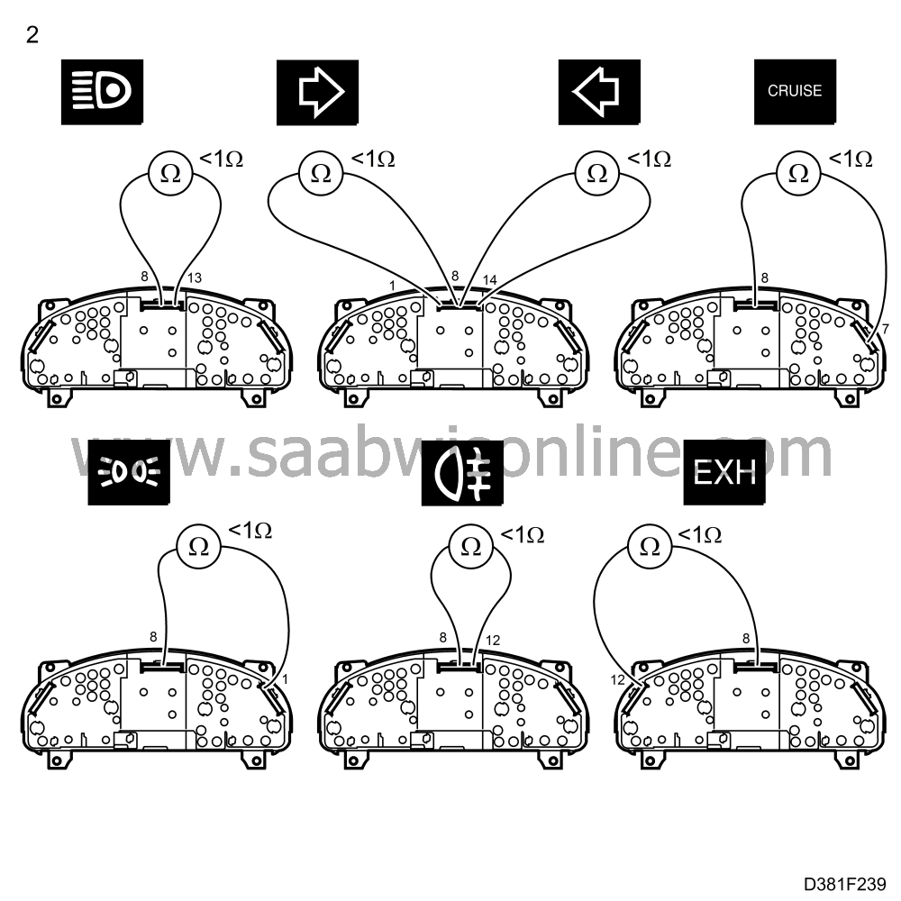
Includes:
|
•
|
Main beam indicator lamp pin 13
(14p)
|
|
•
|
Lights-on indicator lamp pin 1 (white 12p)
|
|
•
|
Rear fog light indicator lamp pin 12 (14p)
|
|
•
|
LH direction indicator repeater lamp pin 14 (14p)
|
|
•
|
RH direction indicator repeater lamp pin 1 (14p)
|
|
•
|
CRUISE indicator lamp pin 7 (white 12p)
|
|
•
|
EXH indicator lamp pin 12 (black 12p)
|
The above indicator and repeater lamps are grounded in the main instrument
display panel and supplied with battery voltage from their respective systems outside the main
instrument display panel.
Fault symptoms
Indicator lamp does not light up when activated.
Diagnostic procedure
|
1.
|
If the indicator lamp does light up when it
should, start by checking whether the lamp's fuse is intact. If the fuse is intact, the bulb
is probably faulty and will have to be changed. If the replacement bulb still fails to light up
when activated, check that the new bulb is ok by fitting it in place of another bulb in the main
instrument display panel that does light up.
|
|
2.
|
Check the conductive foil on the rear of the main instrument display panel for an
open circuit between the bulb's pin in the connector and the foil's corresponding
connector.
If there is an open circuit in the conductive foil, change the foil.
If the conductive foil is intact, there is probably an open circuit in the wiring to the
lamp's sensor. Continue with point 3.
|
|
3.
|
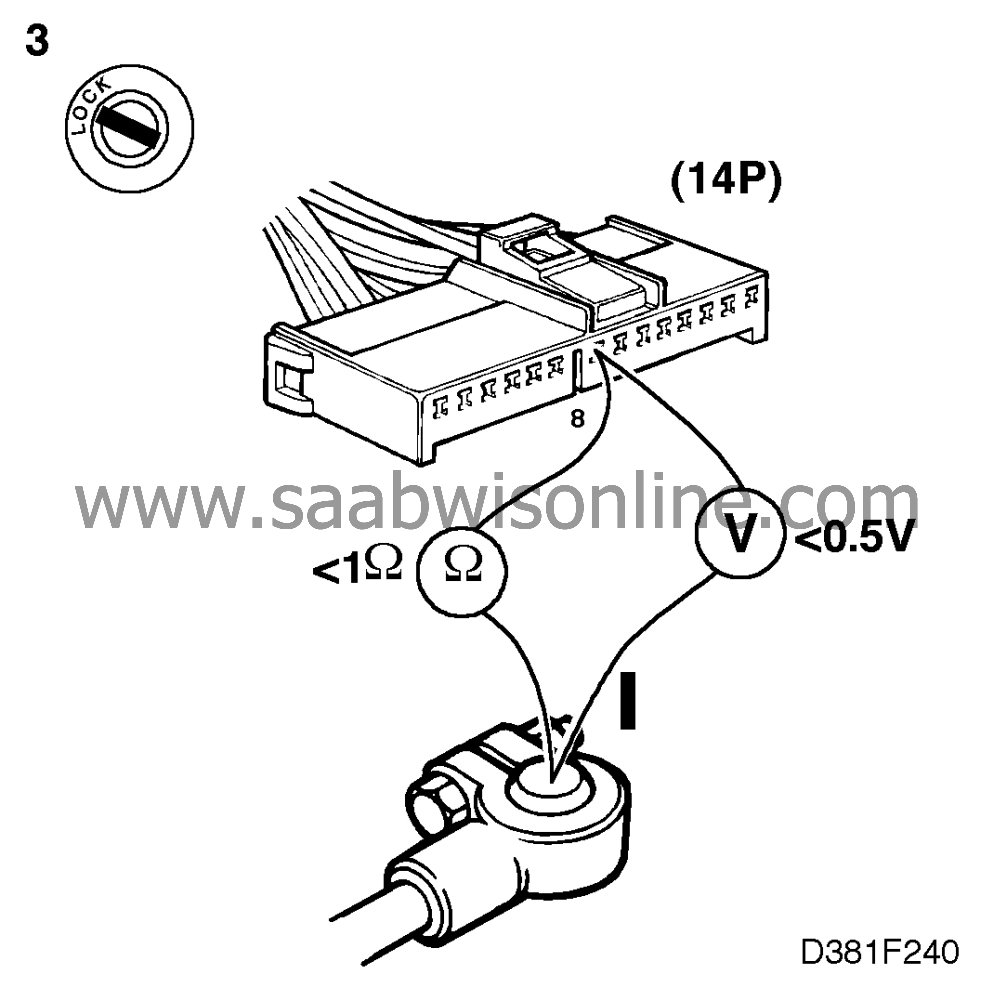
Check the ground connection of the wiring harness by taking a reading across
BATT- and pin 8 (14p) of the connector. The reading obtained should be < 0.5 V.
|
|
4.
|
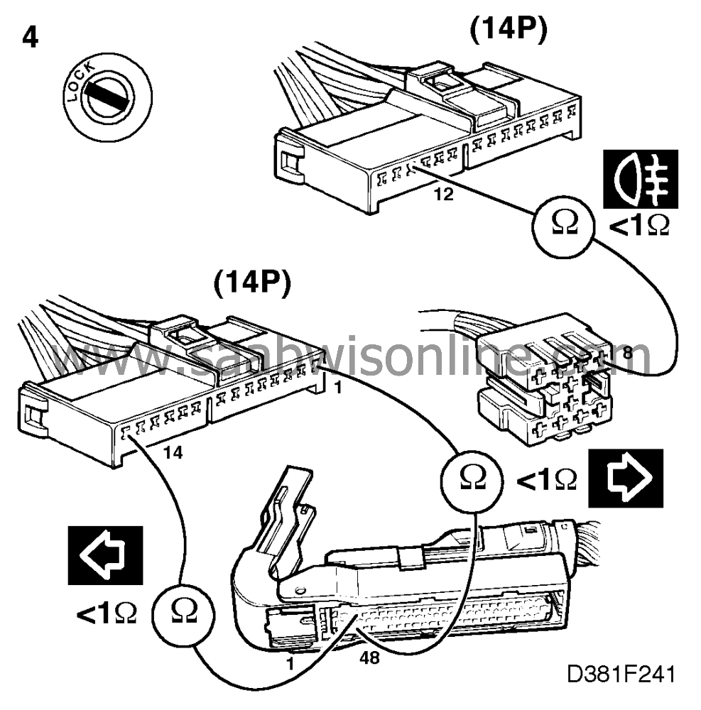
Check the wiring for an open circuit between the main instrument display panel
and the bulb's sensor by measuring the resistance.
|
Lamp
|
Main instrument display
panel pin
|
Sensor
pin
|
Main beam
|
13 (14p)
|
8
|
Lights on
|
1 (12p-1)
|
6
|
Rear fog light
|
12 (14p)
|
8
|
RH direction indicators
|
1 (14p)
|
1
|
LH direction indicators
|
14 (14p)
|
48
|
CRUISE
|
7 (12p-1)
|
8
|
EXH
|
12 (12p-2)
|
2
|


