P1812 , P1813
Symptom: Disturbances in lock-up and gear-shifting functions at higher temperatures.
Transmission fluid temperature sensor, shorted to ground (P1812), or open circuit or shorted to B+ (P1813).
Fault symptom
Disturbances in lock-up and gear-shifting functions at higher temperatures.
Condition
P1812:
Shorting to ground.
P1813:
Shorting to battery voltage or open circuit and if the transmission control module reads a fluid temperature lower than -10°C when the engine has been running for about 5 minutes.
Diagnostic help
The current fluid temperature can be checked using the diagnostic tool. Select "READ FUNCTIONS". Select "OIL TEMPERATURE". With the engine and transmission warmed up, nominal fluid temperature is about 80°C and about 1.1 V.
Check the wiring
Intermittent faults may occur as a result of temporary short circuits and breaks in the wiring. Jiggle the leads at several places and in different directions to reveal any faults in the wiring harness, including connectors. Observe the multimeter, test lamp or ISAT scan tool while carrying out this check.
Diagnostic procedure
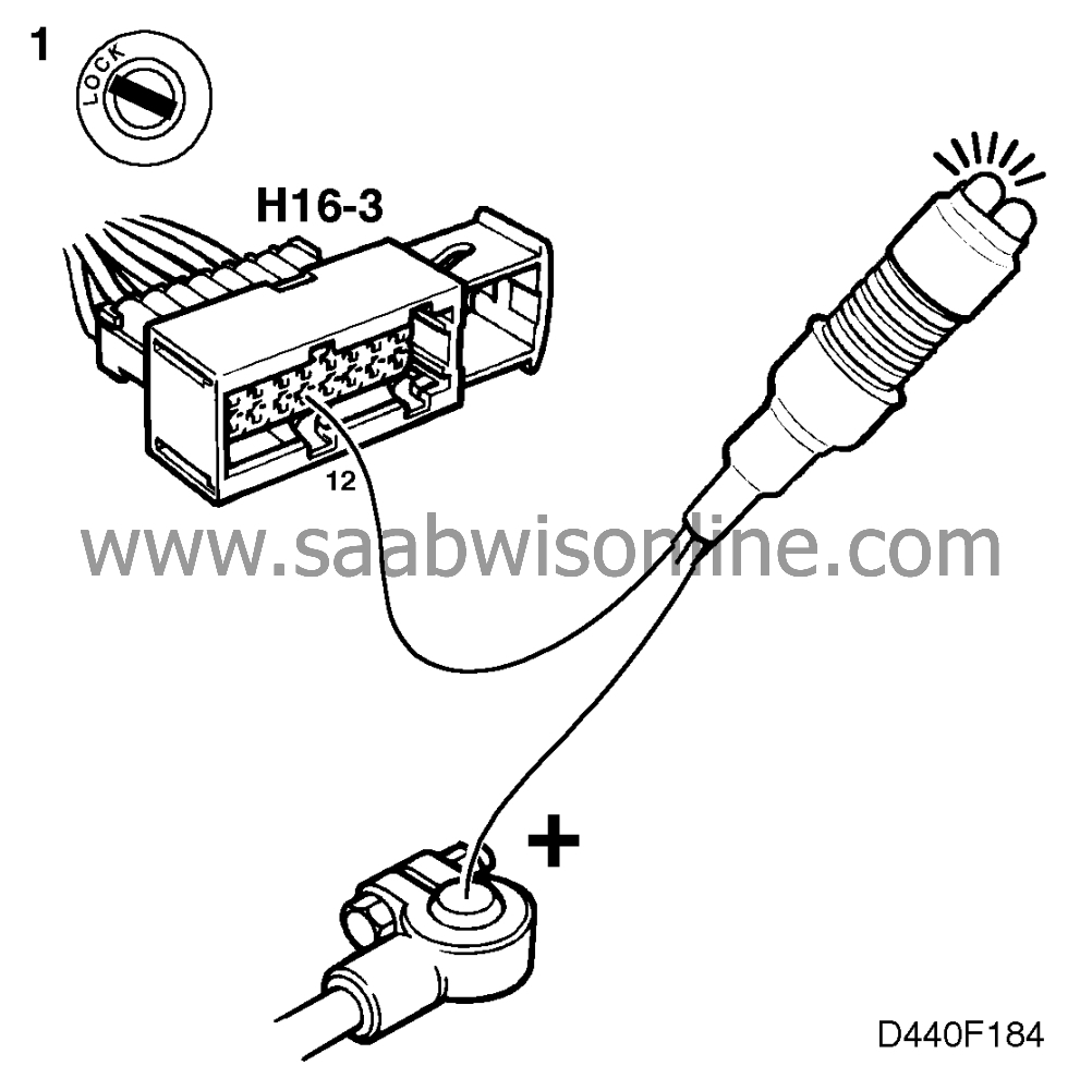
1 Check the fluid temperature sensor's connection to ground

 Unplug connector H16-3 (16-pin connector located behind the battery) and connect a test lamp to pin 12 of the female connector and battery positive (B+).
Did the test lamp light up?
Continue with point 2.
Repair or replace the wiring (including connectors) between connector H16-3, pin 12 of the female connector, and grounding point G4.
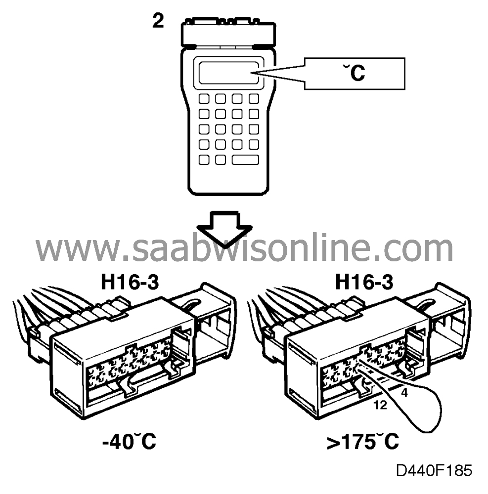
2 Check the transmission control module's signal input

|
-
|
Connect the Scan tool diagnostics instrument.
|
|
-
|
Turn the ignition switch to the ON position.
|
|
-
|
Select "READ FUNCTIONS".
|
|
-
|
Select "OIL TEMPERATURE".
|
|
-
|
With pin 12 open, the diagnostic tool should display a reading of less than -40°C.
|
|
-
|
With a jumper between pin 4 and pin 12, the diagnostic tool should display a reading greater than 175°C.
|
Are both readings OK?
Continue with point 3.
Continue with point 4.
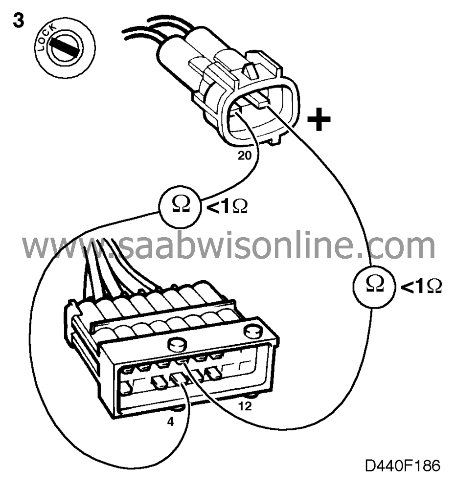
3 Check the wiring
 Check the continuity of the wiring between • pin 4 of connector H16-3 and the temperature sensor's connector (the pin marked 20). • pin 12 of connector H16-3 and the temperature sensor's connector (the unmarked pin).
Is the wiring OK?
Change the temperature sensor and proceed to point 5.
Rectify the fault and continue with step 5.
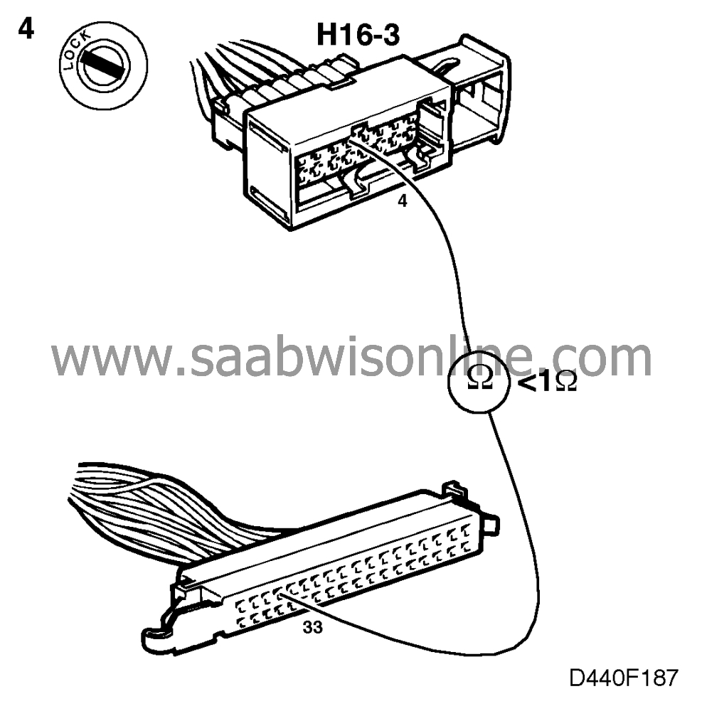
4 Check the wiring connected to the transmission control module

Check the continuity of the wiring between pin 4 of female connector H16-3 and pin 33 of the transmission control module.
Is the wiring OK?
Continue with point 5.
Rectify the fault and continue with step 5.
5 Final check

Clear the diagnostic trouble code, drive the car on test at varying engine loads and speeds for 5 minutes and obtain readouts of any diagnostic trouble codes that are generated.
Does the diagnostic trouble code recur?
Continue with
 .
.
The remedial action taken was correct.


