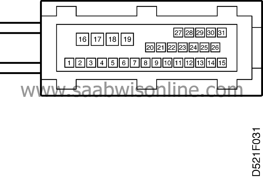
Test readings, control module connections
| Test readings, control module connections |
Scope
Test readings and instructions for measuring signals and signal levels on the ABS control module are given in the following pages.| Points to remember: |
| • |
Measurements should be taken directly from the electronic control module sensor connector. Remove the electronic control module connector.
|
|
| • |
Some voltage levels must be regarded as guiding values. Use your common sense when judging whether a reading is correct or not.
|
|
| • |
If any test reading is incorrect, use the wiring diagram to trace the leads, connectors or components which you consider ought to be checked more thoroughly.
|
|
| • |
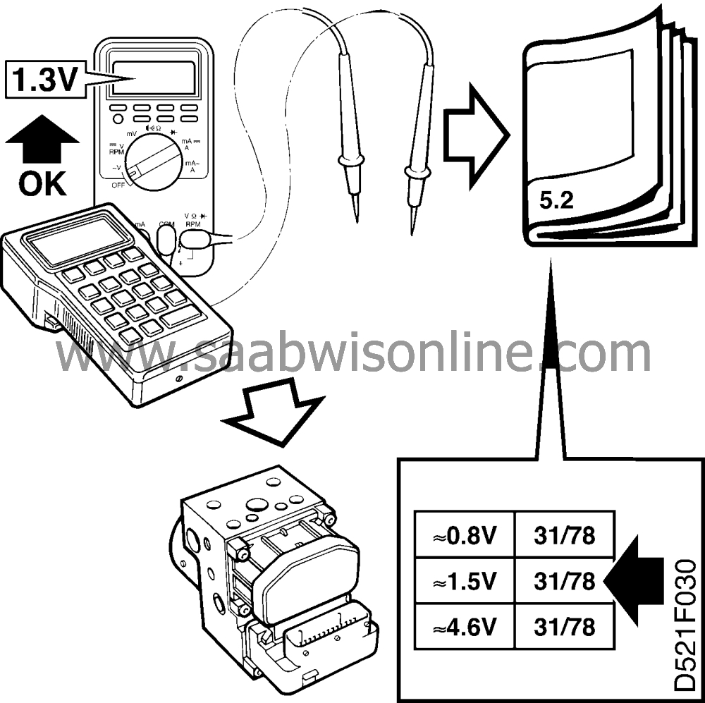
Page references in the table refer to the page on which the description of operation of the signal concerned will be found, and also to the fault diagnosis schedule containing a complete description of the diagnostic procedure to be followed.
|
|
| • |
If nothing else is indicated the ignition timing should be disconnected.
|
|
| • |
The test reading given concerns calibrated FLUKE 88/ 97.
|
|||||||
> = Greater than < = Less than » = Approximately equal to ∼ = Alternating current
| Important | ||
|
Test reading at the electronic control module sensor connector, unless otherwise stated |
||
|
Pin
|
Colour
|
Component/Function
|
in/Out
|
Test condition
|
Test reading
|
Across X-Y
|
|
1
|
YE
|
Wheel sensor RR Reference ground
|
In
|
Rotate the wheel 1 turn/second
|
>100 mV AC
|
1-2
|
|
2
|
BK
|
Wheel sensor RR Signal input
|
In
|
Rotate wheel 1 rev/sec.
|
>100 mV AC
|
2-1
|
|
3
|
BK
|
Wheel sensor FR Reference ground
|
In
|
Rotate wheel 1 rev/sec.
|
>100 mV AC
|
3-5
|
|
4
|
|
Not used
|
|
|
|
|
|
5
|
YE
|
Wheel sensor FR Signal input
|
In
|
Rotate wheel 1 rev/sec.
|
>100 mV AC
|
5-3
|
|
6
|
BK
|
Wheel sensor FL Reference ground
|
In
|
Rotate wheel 1 rev/sec.
|
>100 mV AC
|
6-7
|
|
7
|
YE
|
Wheel sensors FL Signal input
|
In
|
Rotate wheel 1 rev/sec.
|
>100 mV AC
|
7-6
|
|
8
|
BK
|
Wheel sensor RL Reference ground
|
In
|
Rotate wheel 1 rev/sec.
|
>100 mV AC
|
8-9
|
|
9
|
YE
|
Wheel sensor RL Signal input
|
In
|
Rotate wheel 1 rev/sec.
|
>100 mV AC
|
9-8
|
|
10
|
|
Not used
|
|
|
|
|
|
11
|
WH/BK
|
Data link
|
in/Out
|
|
|
|
|
12
|
|
Not used
|
|
|
|
|
|
13
|
|
Not used
|
|
|
|
|
|
14
|
VT
|
Brake light switch
|
In
|
Brake activated
|
B+
|
14-16
|
|
15
|
YE/RD
|
+15 voltage
|
In
|
Ignition on
|
<0.5V
|
15-B+
|
|
16
|
BK
|
Power ground
|
In
|
|
B+
|
16-B+
|
|
17
|
RD
|
+30 voltage
|
In
|
|
<0.5V
|
17-B+
|
|
18
|
RD
|
+30 voltage
|
In
|
|
<0.5V
|
18-B+
|
|
19
|
BK
|
Ground
|
In
|
|
B+
|
19-B+
|
|
20
|
|
Not used
|
|
|
|
|
|
21
|
GY/GN
|
Warning lamp ABS
|
In
|
Ignition on
|
<0.5V
|
21-B+
|
|
22
|
|
Not used
|
|
|
|
|
|
23
|
OG/WH
|
Wheel speed RL
|
Out
|
Slowly rotate the wheel Rotate the wheel 1 turn/second
|
0/approx. 12 V approx. 6 V
|
*)
|
|
24
|
YE/BN
|
Wheel speed RR
|
Out
|
See pin 23
|
See pin 23
|
*)
|
|
25
|
BK/GN
|
Wheel speed FL
|
Out
|
See pin 23
|
See pin 23
|
*)
|
|
26
|
PK/BK
|
Wheel speed FR
|
Out
|
See pin 23
|
See pin 23
|
*)
|

*) = Must be tested at the receiving components


