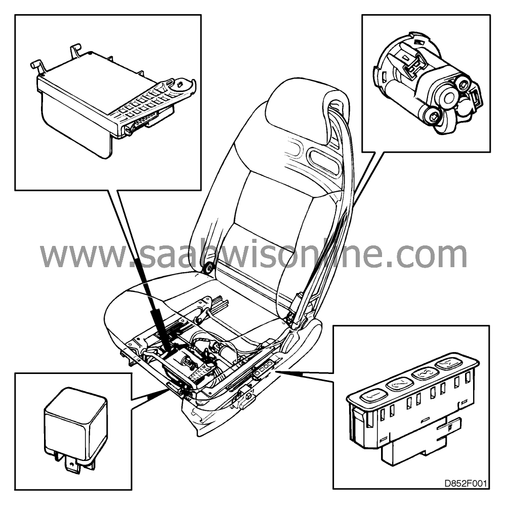
Fault diagnosis, electrically adjustable driver's seat with memory
| Fault diagnosis, electrically adjustable driver's seat with memory |
To provide the memory function, the ordinary electrically adjustable seat is fitted with an electronic unit, a position sensor on each motor, and a switch assembly with four pushbuttons for programming and activating the memory.
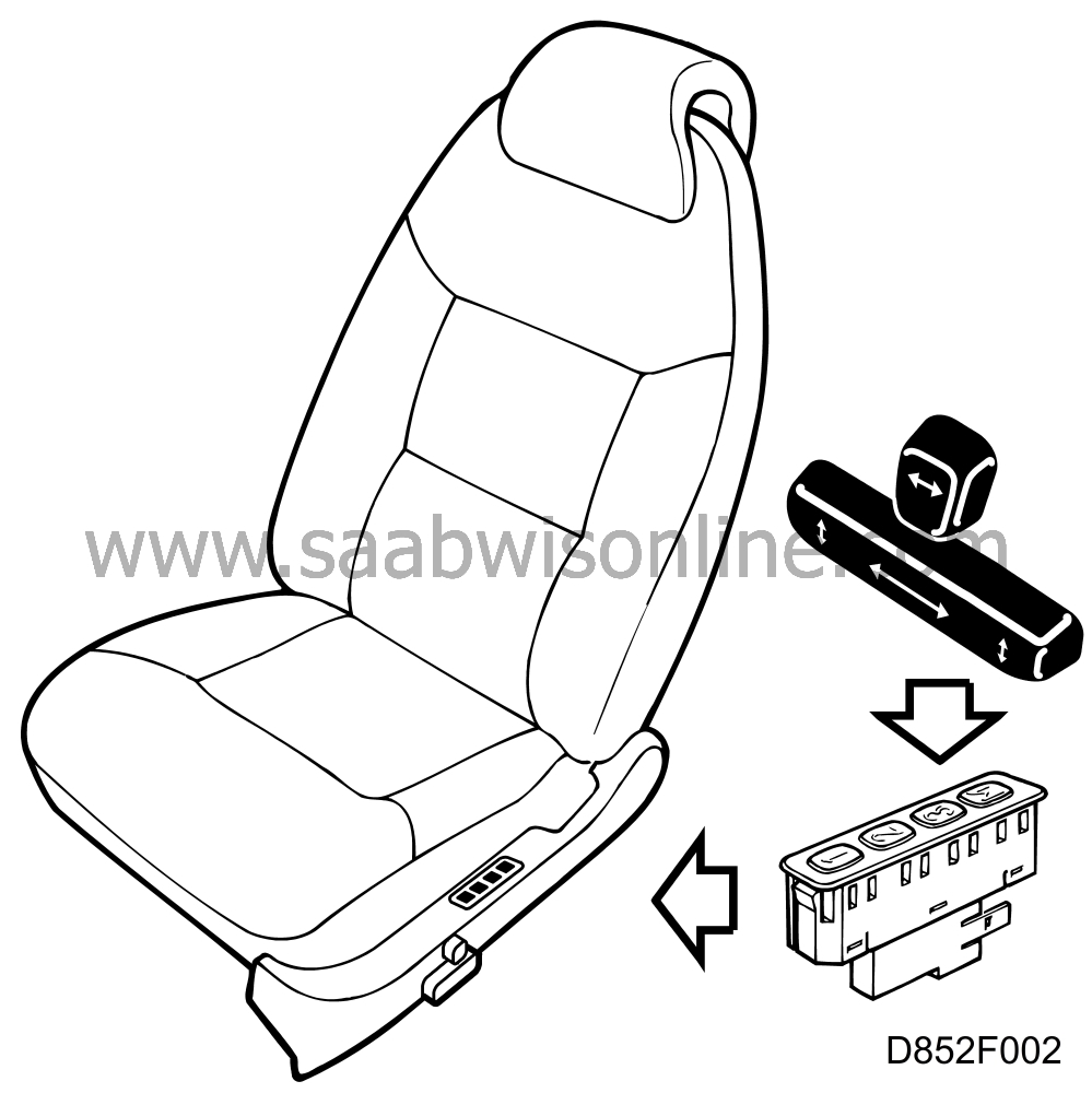
The controls for the memory and programming functions consist off four pushbuttons. Three memory buttons, "1", "2" and "3", and a memory store button "M". Seat settings are stored in the memory as follows:
| • |
Adjust the seat to the desired position by means of the regular setting buttons.
|
|
| • |
Store the setting by simultaneously pressing the "M" button and one of the memory buttons - 1, 2 or 3. To activate the memory function, keep the appropriate memory button depressed until the seat has adjusted itself to the stored setting.
|
|
The electronic unit is supplied with current from the seat relay, which in turn receives a +30 supply via a 30A fuse.
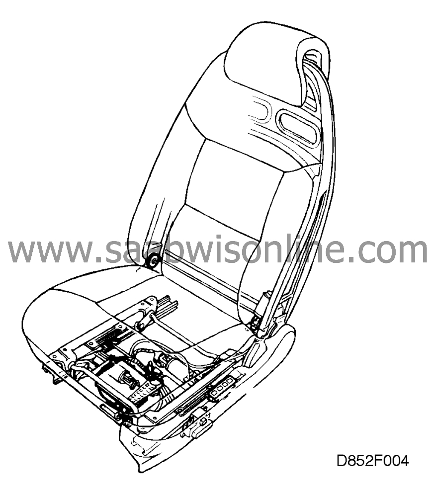
Activation of the seat relay takes place when the ICE (Integrated Central Electronics) unit grounds it. This happens when +54 is active or when any door is open.
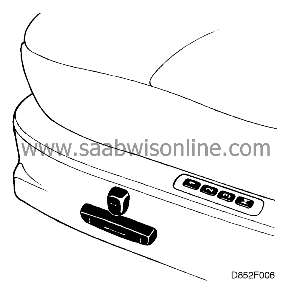
Motors, position sensors (potentiometers) and switches are in their turn supplied with current via the electronic unit. The electronic unit continuously monitors the switches and when a valid combination of switches is activated it performs the corresponding function.
When the motors are operated, the electronic unit monitors the current consumption of each motor and the position of the seat via the position sensors.
The electronic unit also tests the system. Faults it discovers are stored in the form of diagnostic trouble codes which can later be retrieved by means of an ISAT.
The position sensors consist of potentiometers mounted on the shaft of each motor. A power supply of about 5 V is applied to pins 1 and 3 of these potentiometers by the electronic unit. When the motor shaft rotates, the voltage on the centre tap of the potentiometer, pin 2, normally varies between 0.4 and 4.6 V. By measuring this voltage the electronic unit can ascertain the setting of the seat.
The seat has a number of switches, one pole of which is supplied with +12 V (battery voltage) from the electronic unit. When a switch is activated, the 12 V supply is returned to the corresponding switch input on the electronic unit. The voltage on the electronic unit's switch input then changes from 0 V to 12 V.

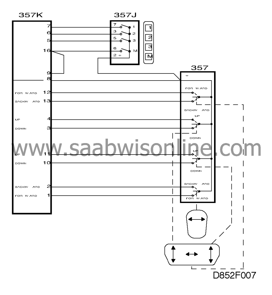
The electronic unit continuously monitors the two sets of pushbuttons and when a valid command is detected it performs the corresponding function, i.e. it controls the motors in the case of manual operation or when a stored setting is recalled, or stores the seat setting if the M button is depressed.
Invalid commands, such as simultaneous activation of several memory buttons or simultaneous activation of more than two switches in the case of manual operation, will result in no function being performed. If a memory store command or a stored setting command is detected at the same time as a manual command, the electronic unit will carry out the manual command.
| Manual adjustment of the seat |

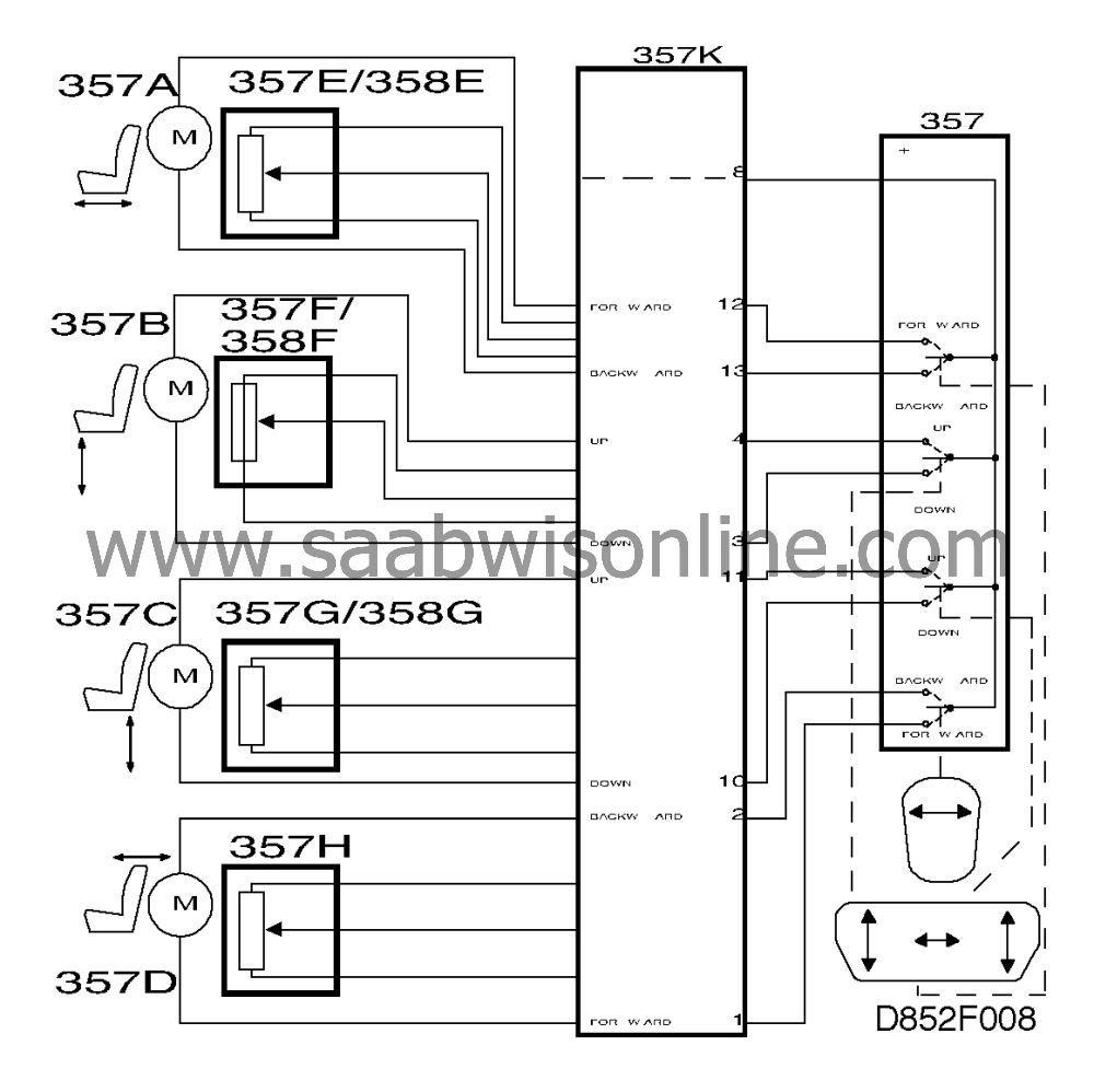
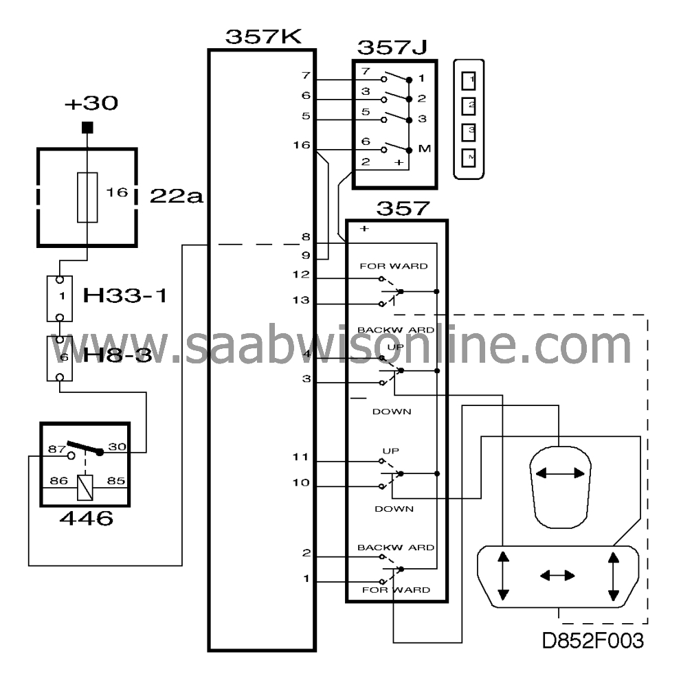
When the seat is manually adjusted, the electronic unit senses which manual control switch is activated and supplies the corresponding motors with current so that they run in the appropriate direction.
The electronic unit allows only two motors to run at the same time and will stop if more than two manual control switches are activated at the same time. The electronic unit supplies these motors with current as long as the relevant manual control switch is activated (but not for longer than one minute).
The backrest has no mechanical stop to limit its rake angle in either direction. Instead, the electronic unit determines the rake angle limits by reading the backrest position sensor. The electronic unit therefore allows no operation of the backrest motor if its position sensor is defective.
| Storing seat settings in the memory |

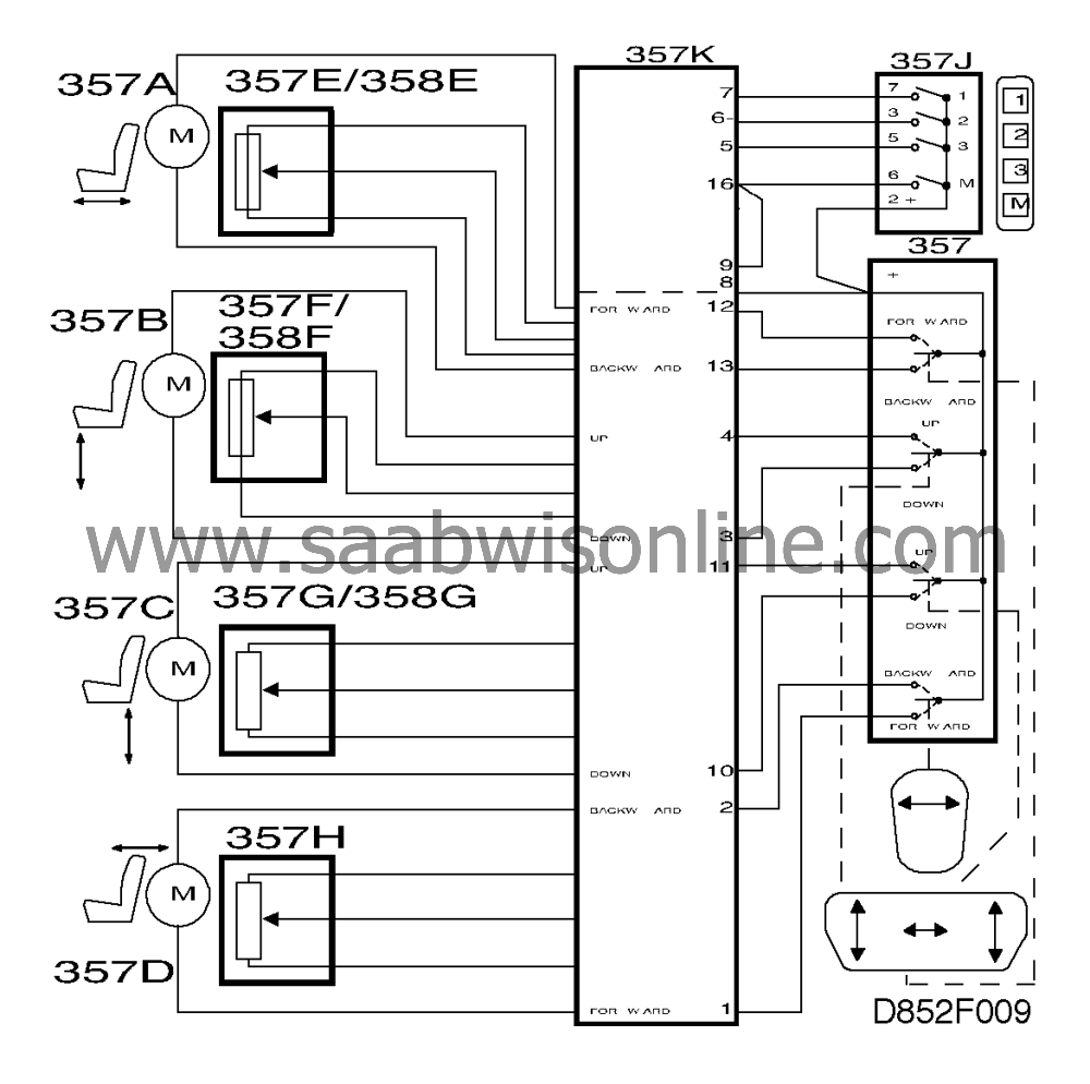
When a seat setting is stored, the electronic unit reads all position sensors and stores their readings in one of the seat memories. The seat memories are non-volatile and retain their information even when the electronic unit is not supplied with current.
If any position sensor is defective, no new seat setting will be stored in the seat memory but the seat setting stored earlier, if any, will be retained.
| Memorized seat settings |
When a memorized seat setting is recalled, the electronic unit reads all position sensors and operates the motors until the seat setting corresponds to the setting stored in the seat memory, or until the memory button is released.
If the electronic unit detects a fault in any position sensor, or if the seat moves too slowly in any direction, the corresponding motor will be stopped.
| Diagnostics |
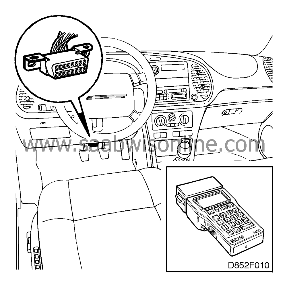
Faults detected by the electronic unit are stored in the form of diagnostic trouble codes. These codes can subsequently be retrieved by connecting an ISAT to the test socket located under the dashboard next to the steering column. Using the ISAT, commands can also be given for obtaining readouts from each individual switch and all position sensors.
| Internal self-test |
The electronic unit tests certain of its own components. If a fault is detected, a diagnostic trouble code for a control module fault is generated.
| Testing of external components |
All position sensors are tested when seat settings are stored in the memory and when stored seat settings are recalled. The backrest position sensor is also tested when the backrest is adjusted by means of the manual control switches. If a position sensor is defective, it will only be possible to operate the corresponding motor manually (exception: the backrest motor cannot be operated if its position sensor is defective) and it will not be possible to store any new seat setting in the memory.
The relevant motors are tested for high current consumption when they are operated by means of the manual control switches or when a setting stored in the memory is recalled. If current consumption is too high, the motor will be stopped. If the electronic unit detects exceptionally high current consumption in any motor four times in succession, it will not permit any more attempts to start it. Fault diagnosis must be carried out and the diagnostic trouble code cleared before it will be possible to operate the motor again.

