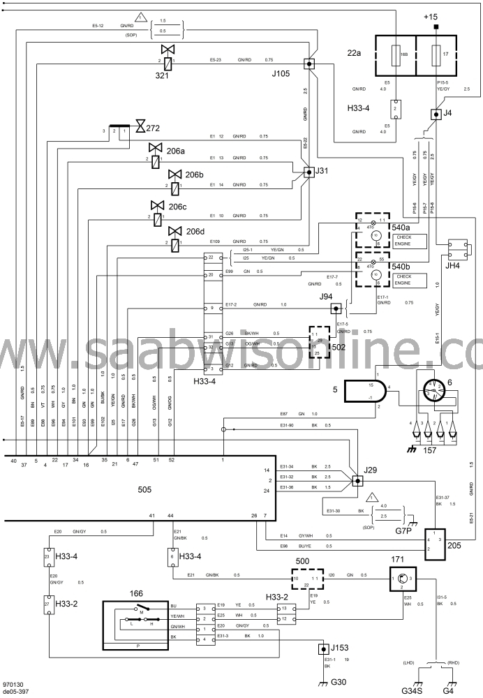
MOTRONIC 2.10.2 wiring diagram (III)
| MOTRONIC 2.10.2 wiring diagram (III) |
| List of components |
|
505
|
MOTRONIC control module. Inside the side trim
below the A
pillar on the right-hand side.
|
|
500
|
ICE control module. Above the relay holder next to
the
steering column.
|
|
502
|
Automatic transmission control module. Behind the
glove box
on the bulkhead partition.
|
|
547
|
ABS control module. Integrated with the brake unit
in the
engine bay.
|
|
229
|
Main relay. In the main fuse box under the
instrument panel.
Location 22B:L (LHD) and 22B:I (RHD).
|
|
102
|
Fuel pump relay. In the main fuse box under the
instrument
panel. Location 22B:I (LHD) and 22B:F (RHD).
|
|
443
|
Engine rpm relay (markets with leaded petrol).
|
|
524
|
Secondary air injection relay. In the main fuse box in
the
engine bay (342:B).
|
|
202
|
Coolant temperature sensor. In the intake manifold,
top left-
hand side of engine.
|
|
203
|
Throttle position sensor. On the throttle body.
|
|
178
|
Knock sensor. In the engine block under the intake
manifold.
|
|
171
|
Anti-freeze thermostat A/C-ACC. Behind the
ACC panel in the
centre console.
|
|
206
|
Injectors. On top of the intake manifold.
|
|
205
|
Mass air flow sensor. On the intake manifold
between the air
cleaner and throttle body.
|
|
272
|
IAC valve. Centrally located by the intake manifold.
|
|
321
|
EVAP canister purge valve. In the engine bay on the
right-
hand side.
|
|
322
|
Connector, coding manual/automatic. By the
MOTRONIC control
module.
|
|
345
|
Crankshaft position sensor. On the front of the
engine block
at the flywheel end.
|
|
166
|
Pressure monitor for the radiator fan, A/C-ACC.
On the drying
agent container between the radiator and grille.
|
|
540A, 540B
|
Main instrument. In the instrument panel.
|
|
549
|
Secondary air injection control valve. On the hose
between
the secondary air injection pump and non-return valve.
|
|
555
|
Camshaft position sensor. In the distributor.
|
|
H16-1
|
16-pin connector. Under the instrument panel by the
steering
column.
|
|
H33-2
|
33-pin connector. On the bracket below the left-
hand A
pillar.
|
|
H33-4
|
33-pin connector. On the bulkhead partition behind
the glove
box.
|
|
G5
|
Grounding point. Under the rear seat on the left-
hand side.
|
|
G7L
|
Grounding point, oxygen sensor. Bracket on rear of
engine.
|
|
G7P
|
Grounding point, power ground. Bracket on rear of
engine.
|
|
G7S
|
Grounding point, signal ground. Bracket on rear of
engine.
|
|
G30
|
Grounding point. On left-hand structural member
behind the battery.
|
|
G33S
|
Grounding point. On the bracket below the left-hand A
pillar.
|


