TCS wiring diagram
| TCS wiring diagram |
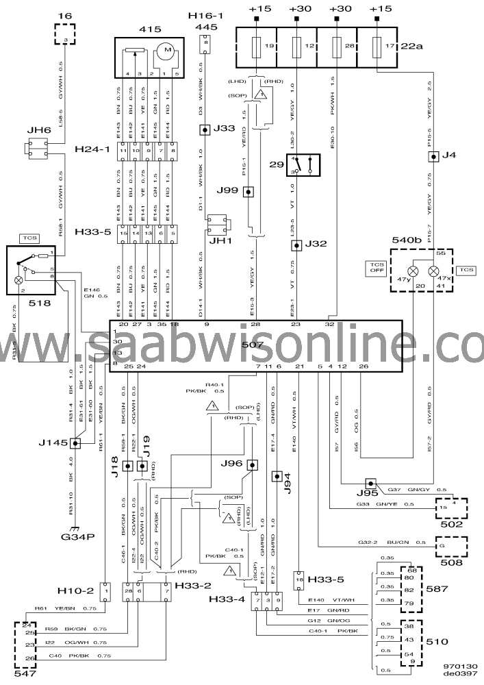
| List of components |
|
29
|
Brake light switch at brake pedal
|
|
415
|
TCS actuator motor on throttle body
|
|
502
|
TCM control module behind the glove
box
|
|
507
|
TCS control module under right-hand front
seat
|
|
508
|
Cruise control module
|
|
510
|
MOTRONIC control module M2.8.1 below right-
hand A pillar
|
|
518
|
TCS switch on centre console
|
|
540B
|
Main instrument 2 in instrument
panel
|
|
547
|
ABS control module integrated in brake
unit
|
|
H33-2
|
33-pin black connector below left-hand A
pillar
|
|
H33-4
|
33-pin connector on bracket at the MOTRONIC
ECM
|
|
H10-9
|
10-pin connector on bracket at the MOTRONIC
ECM
|
|
H16-1
|
16-pin Data Link Connector under instrument panel
on the drivers side
|
|
H16-2
|
16-pin connector adjacent to inlet manifold in engine
bay
|
|
J33
|
(LC 3) approx. 210 mm from the blue 33-pin
connector facing the TCS control module
|
|
J32
|
(CC 68) approx. 320 mm from the brake light switch
facing the TCS control module
|
|
G34S G34P
|
Grounding points below the right-hand A
pillar
|
|
47 X
|
TCS indicator lamp
|
|
47 Y
|
TCS OFF warning lamp
|
This project is supported by memberships and donations. If you use this site, please consider Joining SCNA and/or making a donation.
Our Friends
