Cooling system
| Cooling system |
| FAN VARIANT |
| 1. |
Plug in the scan tool and select "READ FAULT CODES" from the menu. If any trouble codes are present, continue on
 .
.

|
|
| 2. |
To start the radiator fan, select "ACTIVATE RELAY" from the menu and then "RADIATOR FAN LOW".

If a 2-speed radiator fan is fitted, select "ACTIVATE RELAY" and then "RADIATOR FAN HIGH". If the radiator fan does not work, check that a +12 V power supply is present on connector pin 30 of the relay holder for each radiator fan relay. |
|
| 3. |
Connect a jumper lead between connector pins 30 and 87 of the relay holder.
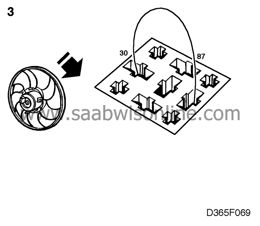
If the radiator fan works, the fault is in the relay. Change the relay. If the radiator fan does not work, continue with point 4. |
|
| 4. |
Unplug the radiator fan connector and check that:
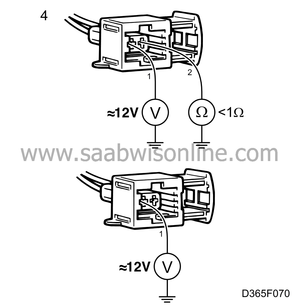
1-speed fan |
|
| • |
a 12 V power supply is present between pin 1 and a good grounding point.
|
| • |
resistance between pin 2 and a good grounding point is less than 1 ohm.
Also check that: 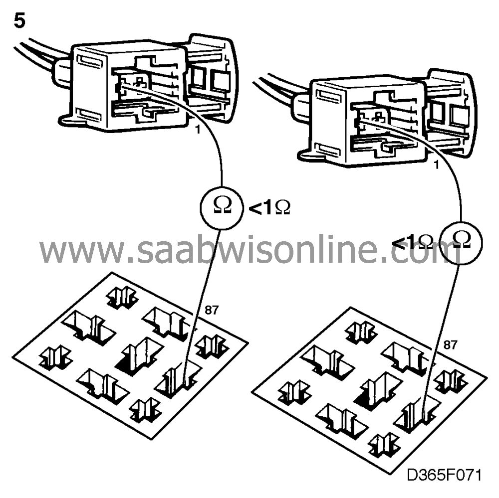
2-speed fan |
| • |
a 12 V power supply is present between pin 1 of the connector and a good grounding point.
|
| 5. |
If not, check the leads for breaks/shorting, as follows:
|
|
| • |
between pin 87 of the relay holder connector and pin 1 of the 1-speed radiator fan connector.
|
| • |
between pin 87 of the relay holder connector and pin 1 of the 2-speed radiator fan connector.
|
| 6. |
If the radiator fan still does not work in spite of the above checks, change the radiator fan motor.
|
|
| A/C pressure switch |
| 1. |
Select "READ VALUES" and then "PRESS. SWITCH 1 AC". Cars for certain markets are equipped with an extra pressure switch and in such cases select "PRESS. SWITCH 2 AC". "
OPEN
" - Fan must be inactivated

" CLOSED " - Fan must be activated |
|
| 2. |
If this is not the case, disconnect the pressure switch, connect a jumper lead between the connector pins and repeat point 1.
|
|
| 3. |
If this does not work, connect a BOB and check the leads for breaks/shorting as follows:
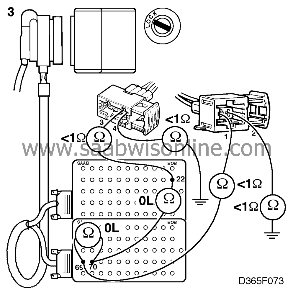
Pressure switch 1 |
|
| • |
between ICE connector pin 22 and pressure switch connector pin 3.
|
| • |
between pressure switch connector pin 4 and a good grounding point.
Pressure switch 2 |
| • |
between ICE connector pin 69 and pressure switch connector pin 1.
|
| • |
between pressure switch connector pin 2 and a good grounding point.
|
| 4. |
If there is no fault in the wiring, change the pressure switch.
|
|
| Cooling system temperature |
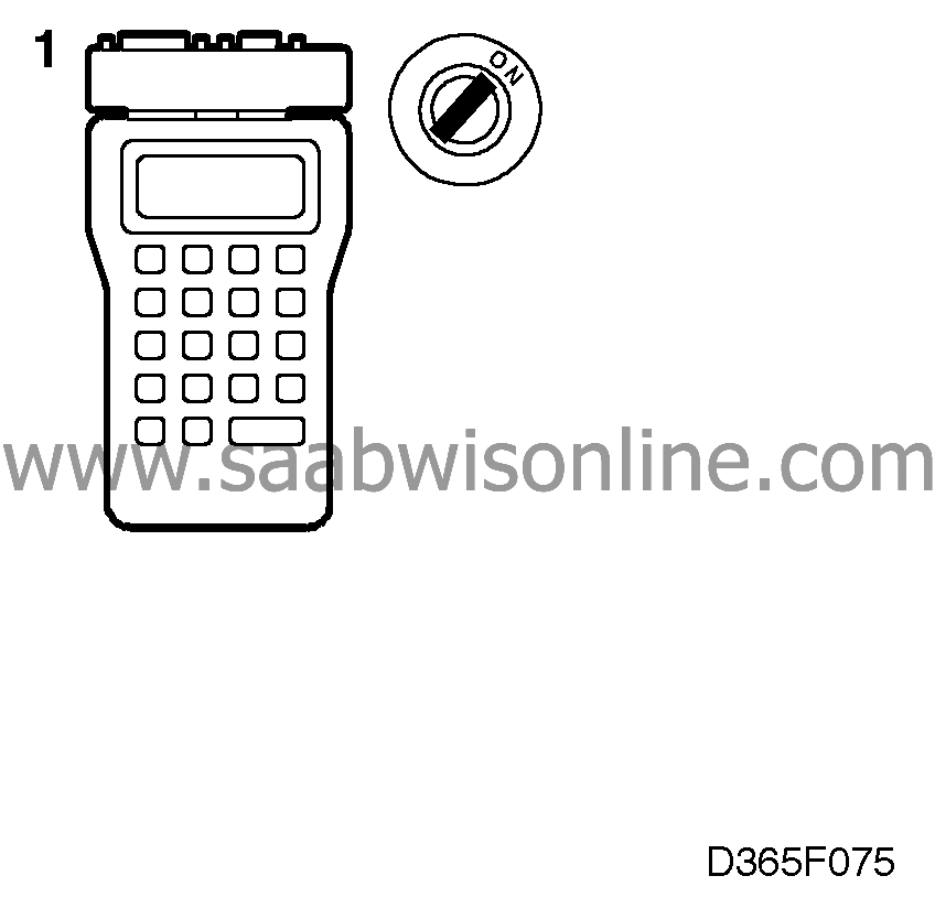
| 1. |
Select "READ FAULT CODES" from the scan tool menu. If any diagnostic trouble codes are present, continue on
.
|
|
| 2. |
Check the temperature gauge in the main instrument display panel by selecting "ACT. INSTR. FUNCT" from the scan tool menu and then "SIM. COOL. TEMP 2" or "SIM. COOL. TEMP 1" This causes the ICE module to simulate a cooling system temperature of between -30 and +130
°
C (-22 and +266
°
F) for 40 seconds.
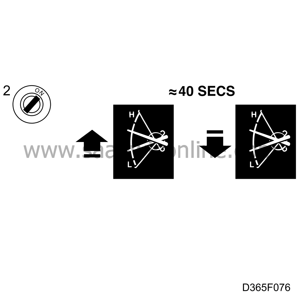
Read the temperature gauge in the car. |
|
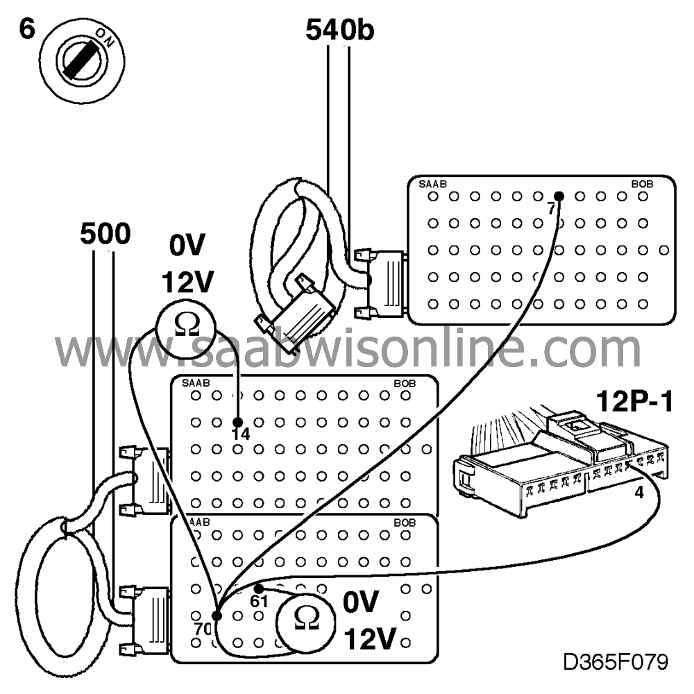
| 3. |
Plug in the BOB and connect a voltmeter:
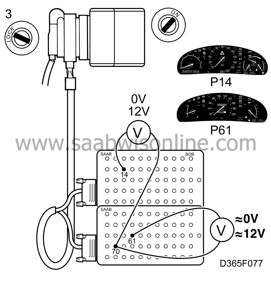
Car equipped with main instrument display panel 1: Plug in the BOB and connect a voltmeter across pins 70 and 61 on the BOB. Car equipped with main instrument display panel 2: Plug in the BOB and connect a voltmeter across pins 70 and 14 on the BOB. Select "ACT. INSTR. FUNCT" and then "TEMP. GAUGE OUT 1" or "TEMP. GAUGE OUT 2" from the scan tool menu. The voltage reading obtained should be: about 0 V with the ignition switch "ON". about 12 V with the ignition switch "OFF". |
|
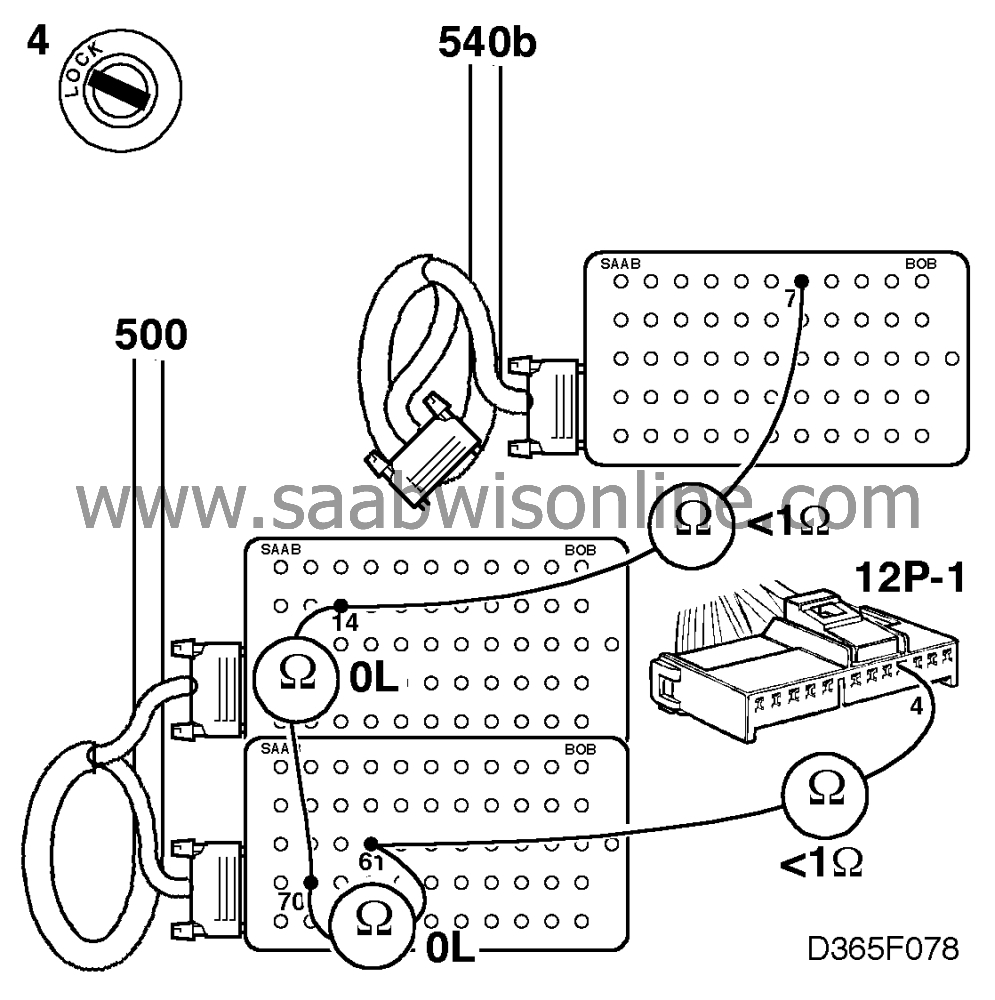
| 4. |
If the voltage readings are not OK, check the wiring for breaks/shorting as follows:
|
|
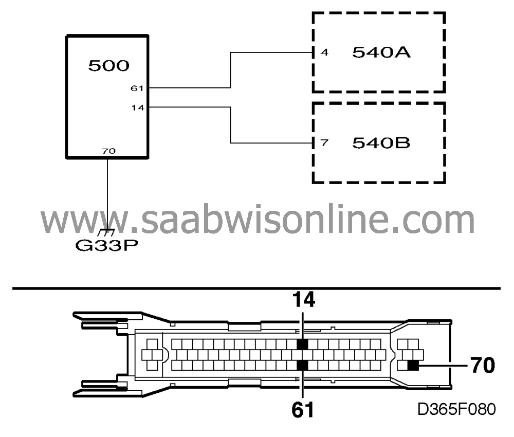
| • |
between pin 61 of the ICE module connector and pin 4 of the main instrument display panel connector (12p-1 main instrument display panel 1).
|
| • |
between pin 14 of the ICE module connector and pin 7 of the main instrument display panel (main instrument display panel 2).
|
| 5. |
If the leads are OK, the fault is probably in one of the control modules.
|
|
| 6. |
Plug in the ICE control module connector and repeat points 2 and 3 while grounding connector pin 4 (12p-1 main instrument display panel 1) or connector pin 7 (main instrument display panel 2) at the same time.
The voltage reading obtained should be 0 V with the ignition switch "ON" and 12 V with it "OFF". If the voltage reading is OK, the fault is probably in the main instrument display panel. Continue fault diagnosis as described in Service Manual 3:5 "Electrical system, Main instrument display panel".
If the voltage reading is not OK, continue on
|
|
| Checking the idling speed increase (MOTRONIC 2.10.2 only) |

| 1. |
Plug in the scan tool and select "READ FAULT CODES" from the menu. If any trouble codes are present, continue on
.
|
|
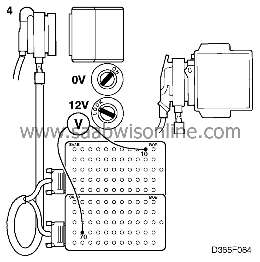
| 2. |
Connect a BOB and take voltmeter readings across connector pins 10 and 70. Check the increase in idling speed by selecting "ACT. OTHER FUNCT" from the menu and then "IDLING INCREASE".
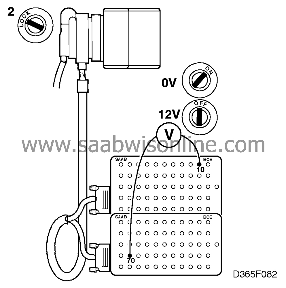
Read the voltmeter to see whether the voltage drops to about 0 V when the ignition switch is "ON" and rises to about 12 V when it is "OFF". |
|
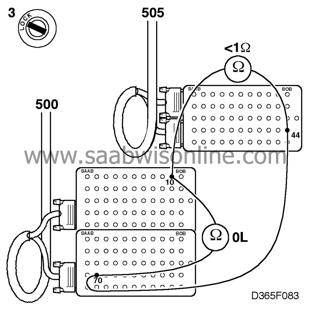
| 3. |
If this is does not work, check the wiring between the ICE control module and the engine management system control module (both control modules unplugged) for breaks/shorting.
|
|
| 4. |
Plug in the engine management system control module and repeat point 2. A reading of 0 V should be obtained when "ON" and 12 V when "OFF".
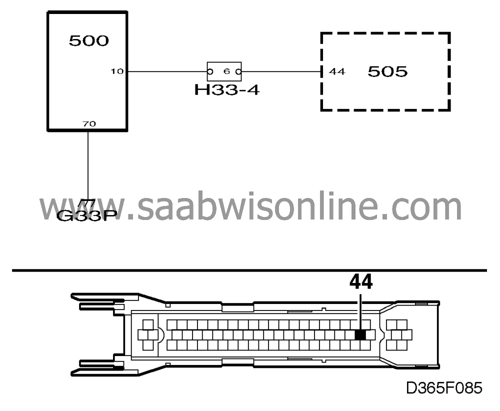
If the voltage reading is OK, the fault is in the engine management system. Continue fault diagnosis as described in Service Manual 2:7.
If the voltage reading is not OK, continue on
|
|
This project is supported by memberships and donations. If you use this site, please consider Joining SCNA and/or making a donation.
Our Friends
