Direction indicators
| Direction indicators |
| 1. |
If only a single lamp is faulty, first check the bulb and its connector.
|
|
| 2. |
If
none
of the direction indicator lamps work, check the direction indicator lamp fuses in the main fuse box in the dashboard.
|
|
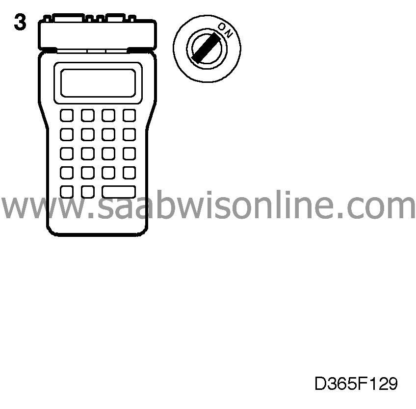
| 3. |
Plug in the scan tool and select "READ FAULT CODES" from the menu. If any trouble codes are present, continue on page
 .
.
|
|
| 4. |
Check the operation of the direction indicators by selecting "ACT. OTHER FUNCT" from the menu and then "LH DIRECT. INDIC." or "RH DIRECT. INDIC."

The direction indicators should now be activated when the ignition switch is "ON". If they work, continue with point 8. |
|
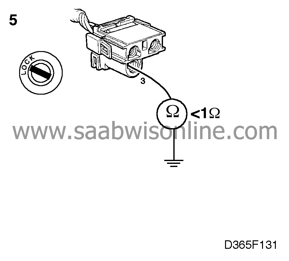
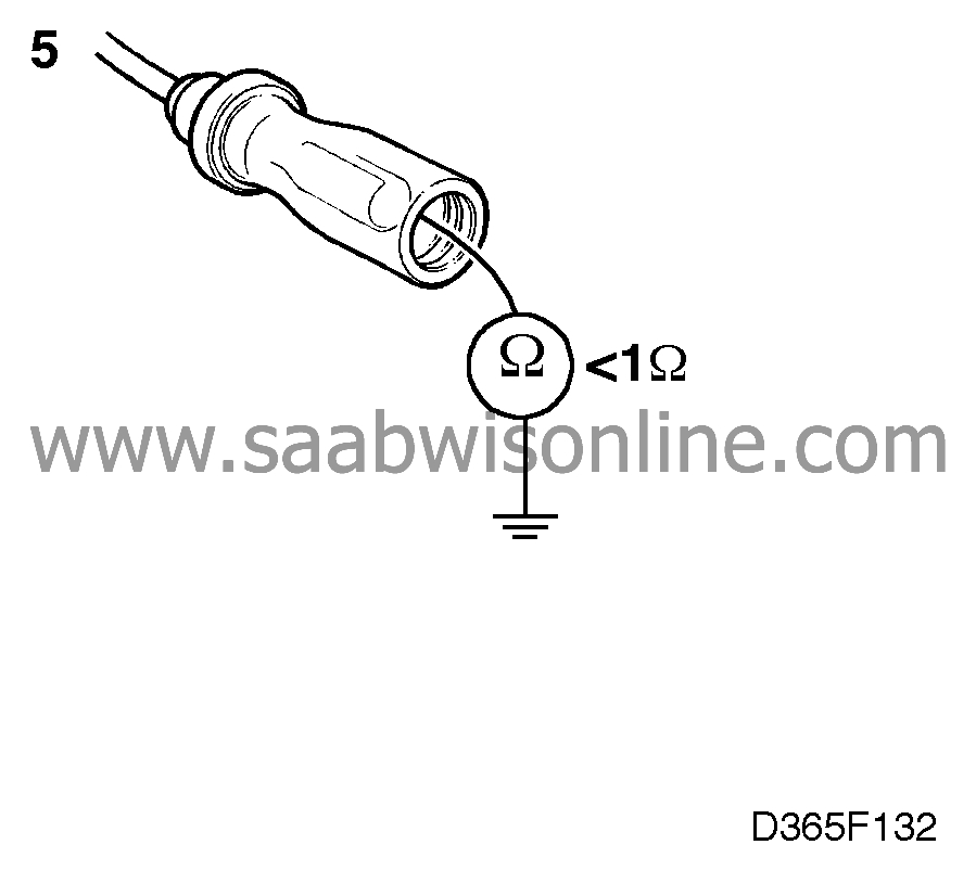
| 5. |
Check the grounding of the direction indicator lamps for breaks/shorting by taking readings of the wiring as follows:
|
|
| • |
between pin 3 of the connector for the front direction indicator lamps and a good grounding point.
|
| • |
between one of the side direction indicator connectors (black lead) and a good grounding point.
|
| • |
between pins 4 (left-hand) and 2 (right-hand) of the rear direction indicator lamp connectors and a good grounding point.

|
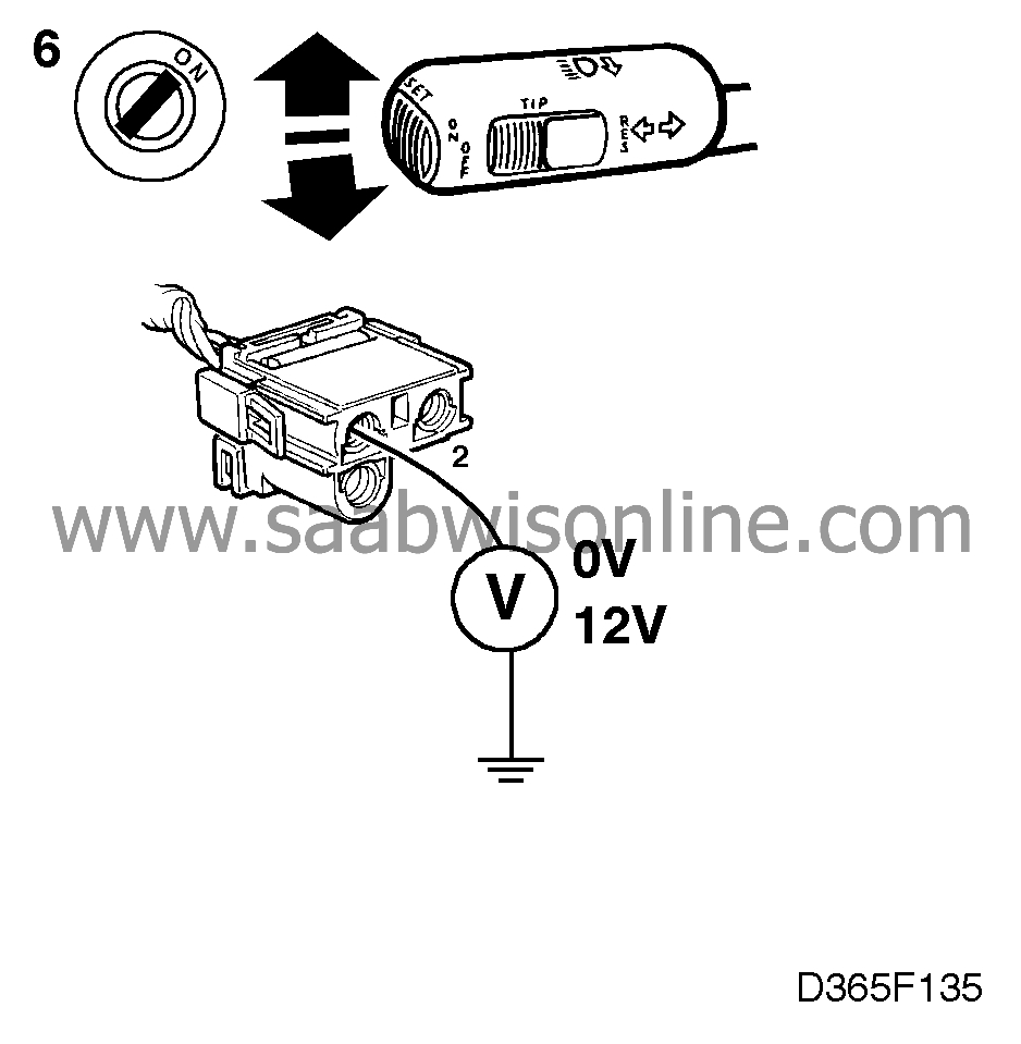
| 6. |
Activate the direction indicator switch and check the power supply to the direction indicator lamps by taking readings as follows:
|
|
| • |
between pin 2 of the connector for the front direction indicator lamps and a good grounding point.
|
| • |
between the left-hand side direction indicator connector (yellow/black lead) and a good grounding point. between the right-hand side direction indicator connector (green/black lead) and a good grounding point
|
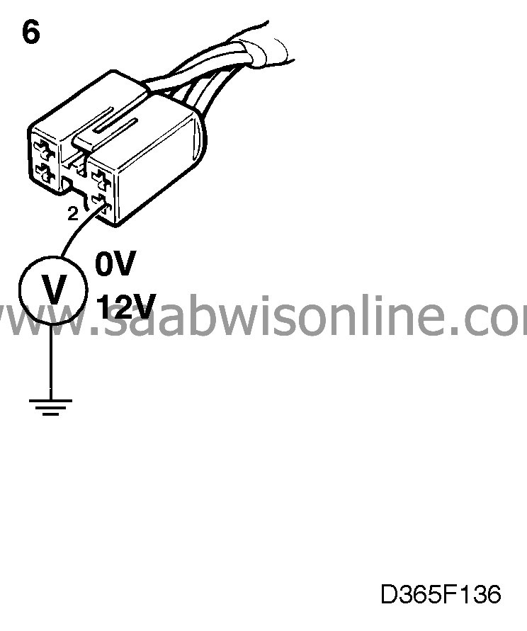
| • |
between pins 2 (left-hand) and 4 (right-hand) of the rear direction indicator lamp connectors and a good grounding point.
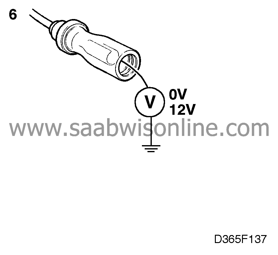
The voltage readings should change between 0 V and 12 V. |
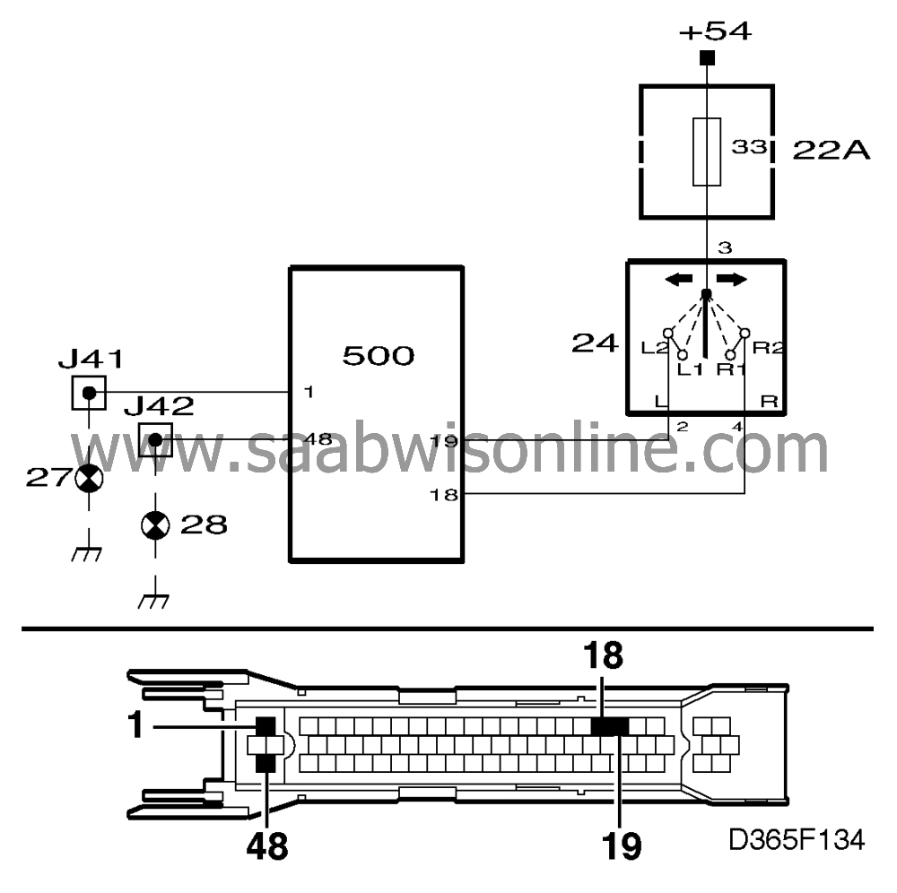
| 7. |
If not, check the wiring for breaks/shorting as follows between ICE module connector pins 1 for left and 48 right and:

|
|
| • |
pin 2 of the connector for the front direction indicator lamps.
|
| • |
the connector for the side direction indicators (yellow/black lead, left and green/black lead, right).
|
| • |
pins 2 (left-hand) and 4 (right-hand) of the connector for the rear direction indicator lamps.
|
| 8. |
Check the power supply to the direction indicator switch by taking a voltmeter reading between pin 3 of the switch connector and a good grounding point.
If no voltage reading is obtained, check the lead between fuse 33 and the switch. |
|
| 9. |
If a voltage reading is obtained, check the direction indicator switch by connecting a jumper lead between pins 2 and 3 of the connector for the left-hand direction indicators and between pins 3 and 4 for the right-hand direction indicators. If the direction indicators work when the pins are connected by jumper leads, the fault is probably in the direction indicator switch. Fit a new switch.

|
|
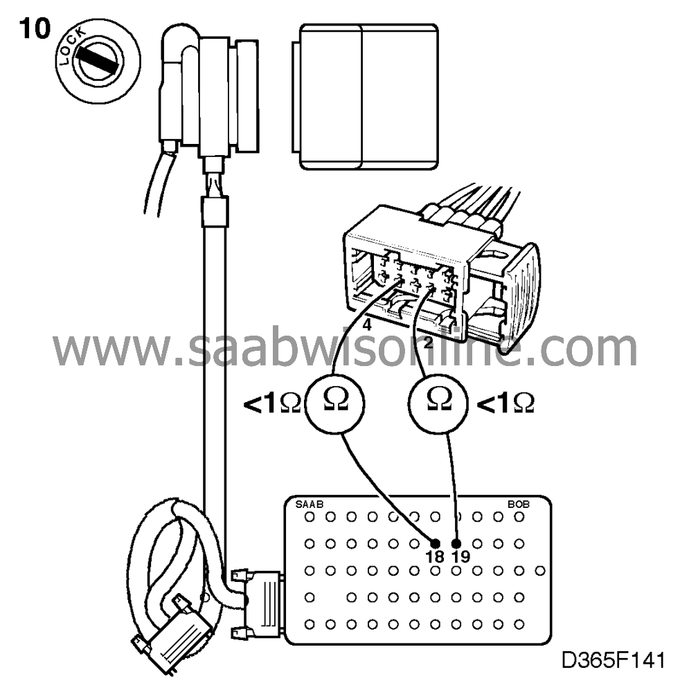
| 10. |
If this does not work, check the leads for breaks/shorting by taking resistance readings as follows:
|
|
| • |
across pin 18 of the ICE control module connector and pin 4 of the direction indicator switch connector.
|
| • |
across pin 19 of the ICE control module connector and pin 2 of the direction indicator switch connector.
|
| 11. |
Continue fault diagnosis as described on
.
|
|
This project is supported by memberships and donations. If you use this site, please consider Joining SCNA and/or making a donation.
Our Friends
