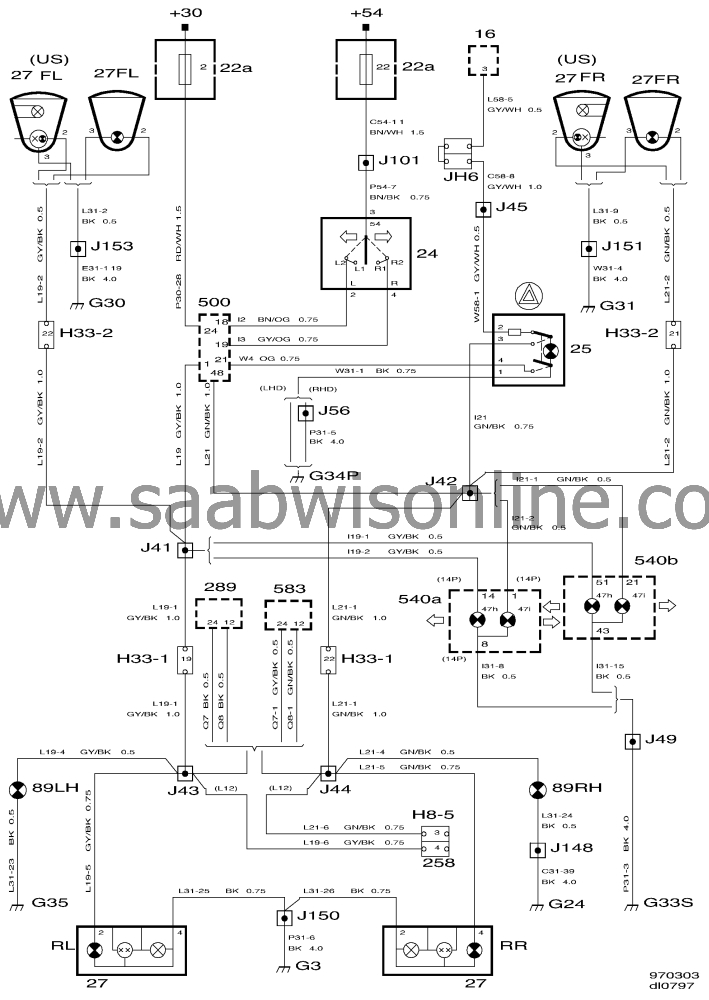
Direction indicators, hazard flashers
| Direction indicators, hazard flashers |
| Flashers |
Current is supplied via fuse 33 to the direction indicator stalk switch and then to pins 18 (left) and 19 (right) of ICE control module 500.
The ICE control module sends current pulses to the left-hand and right-hand direction indicator lamps.
In positions L1 and R2 of the direction indicator stalk switch, the left-hand and right- hand direction indicator lamps will flash as long as the stalk switch is held in the corresponding position.
In positions L and R, activation of the direction indicators takes place in the same manner except that the stalk switch returns automatically to the neutral position when the steering wheel is returned to the straight-ahead position.
The two indicator lamps 47H (left) and 47I (right) are connected in parallel with the direction indicator lamps.
Direction indicator lamps on a trailer, if any, are supplied with current via connector 258 (H8-5).
| Hazard flashers |
Current is supplied to pin 24 of the ICE control module via fuse 2.
When the hazard flashers switch is actuated, the contacts close and pin 21 of the ICE control module is connected to ground.
The ICE control module supplies current pulses to the left-hand and right-hand direction indicator lamps, to the two indicator lamps 47H and 47I in the main instrument display panel and to side direction indicators 89 and 90, which all start to flash.
When the switch is actuated, the indicator lamp in the switch button will also light up.
Direction indicator lamps on a trailer, if any, are supplied with current via connector 258 (H8-5).


