Fault diagnosis, speedometer and odometer (MIU 2)
|
Fault diagnosis, speedometer and odometer (MIU 2)
|
Fault symptom
Speedometer needle does not move.
Odometer and trip meter stationary.
Radio AVC adjustment does not work.
Some trip computer functions do not work.
If the speed signal sent to the ABS control module is faulty, the ANTI LOCK warning lamp will light up. Continue fault diagnosis as described in Service Manual 5 "Brakes".
Diagnostic procedure
1.
|
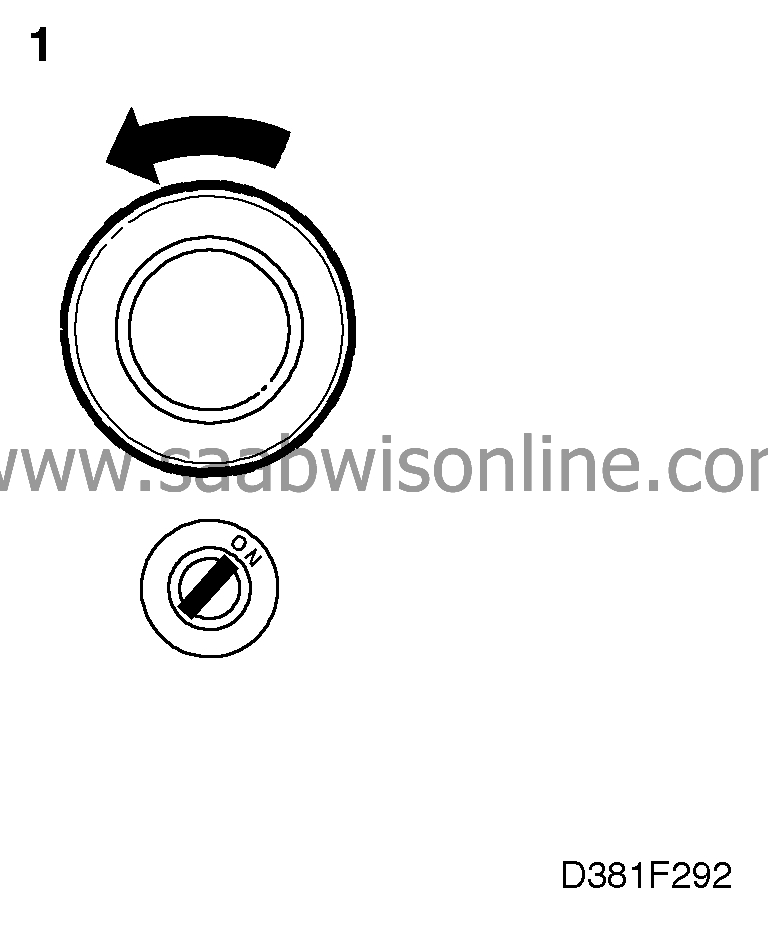
Jack up the LH rear wheel and spin it by hand or start the engine and engage a gear.
|
2.
|
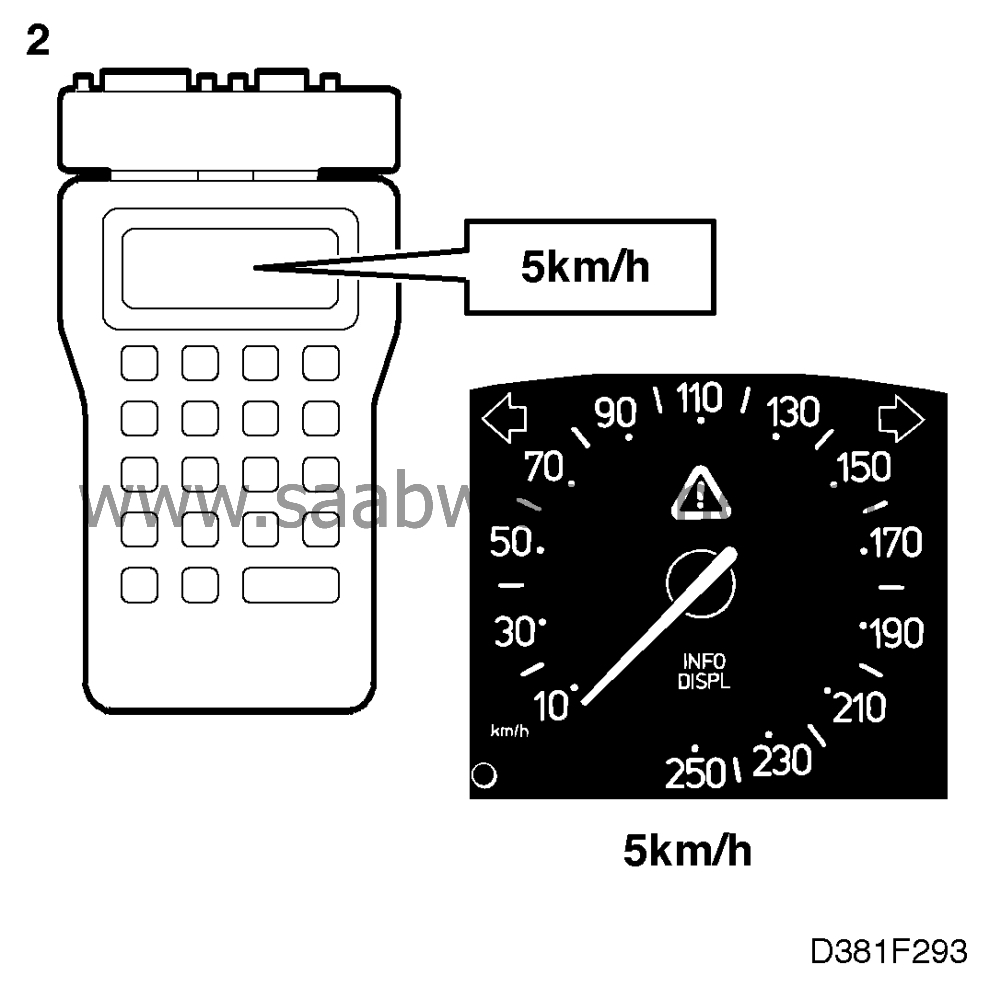
Connect the ISAT Scan Tool and select "READ VALUES" followed by "SPEED".
|
3.
|
If the speed signal is OK, the corresponding speed (in km/h) should be shown on the Scan Tool's display. If this is the case, continue with point 7.
|
4.
|
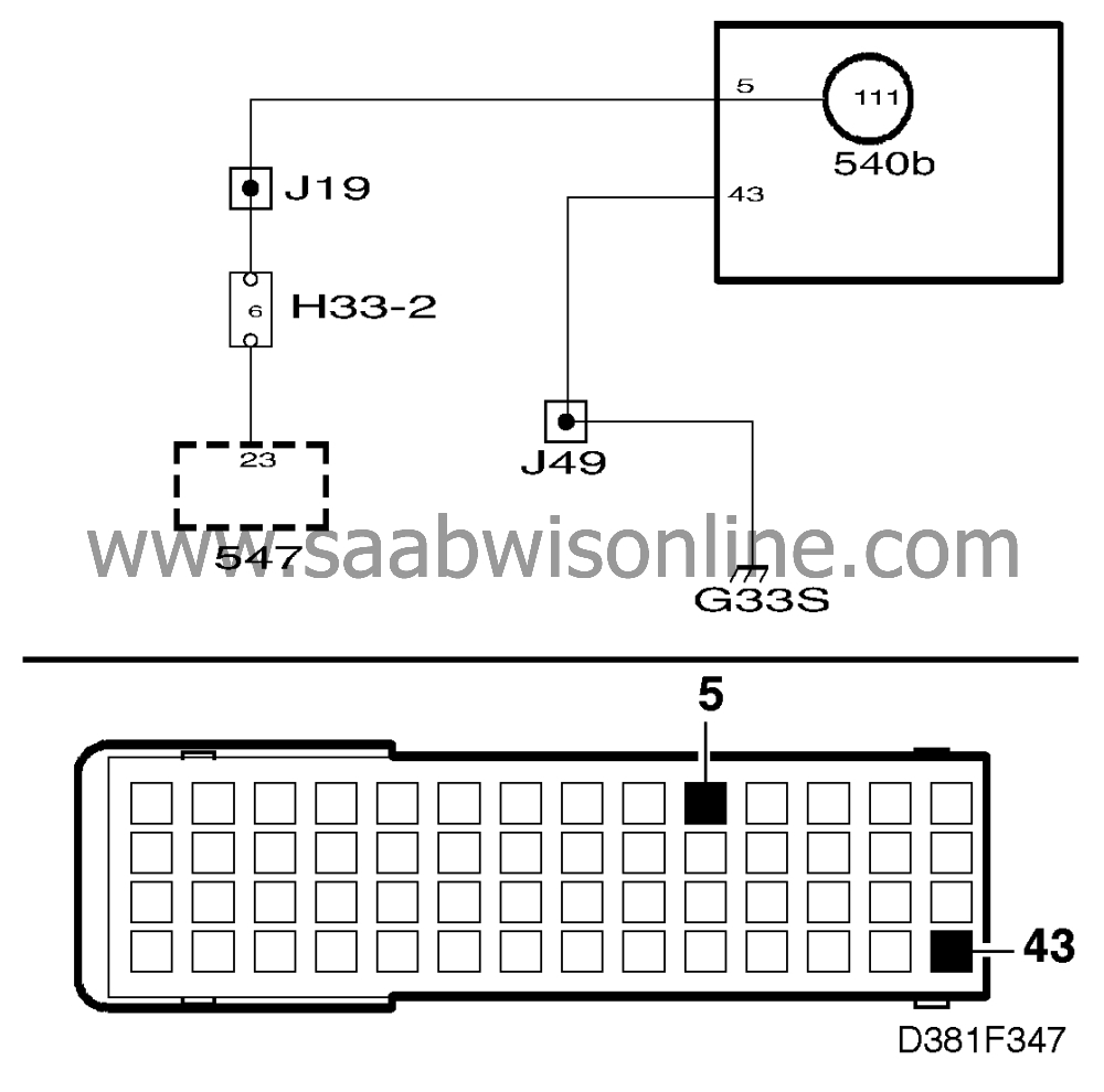
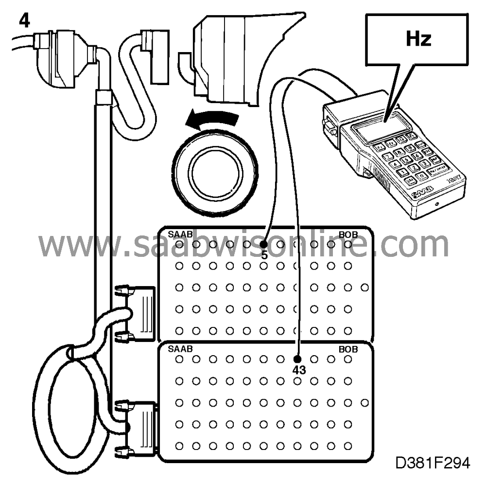
If no speed signal is present, check the signal sent to the main instrument display panel by connecting a BOB to its 56-pin connector (the main instrument display panel should not be connected).
Connect the ISAT scan tool's test leads to pin 5 and ground. Then select "TEST" followed by "PULSE". Spin the rear wheel and check whether pulses are generated.
About 15 Hz at 1/2 revolution per second.
If pulses are generated, proceed to point 8.
|
5.
|
If no pulses are generated, check the wiring by connecting another BOB to the ABS control module's connector.
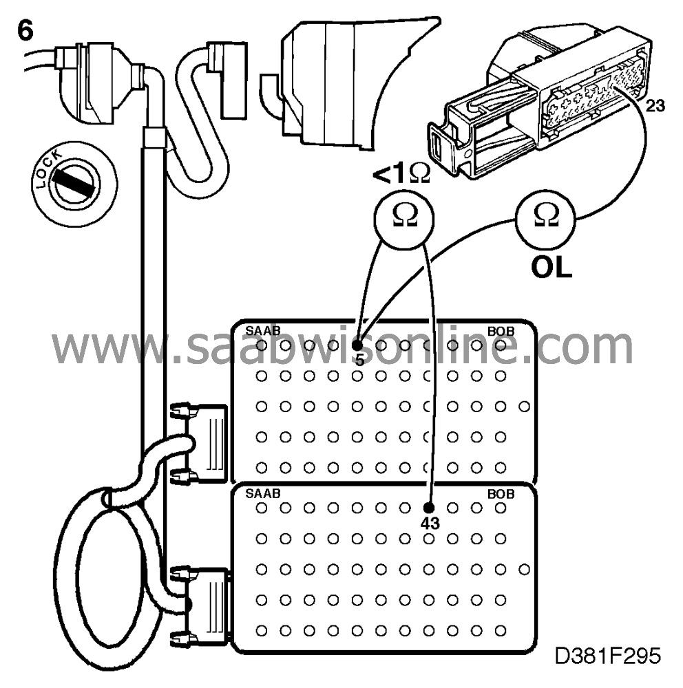
The main instrument display panel and the ABS control module should not be connected.
|
6.
|
Take a reading across pin 5 on the BOB connected to the main instrument display panel and pin 23 on the other BOB to check for an open circuit or shorting to ground.
If the wiring is OK, continue fault diagnosis as described in Service Manual 5 "Brakes".
|
7.
|
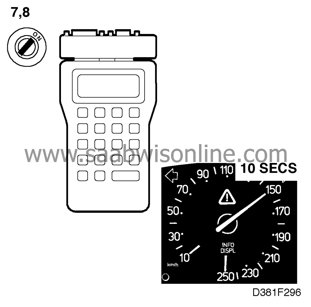
Select "TEST FUNCTIONS" followed by "SPEEDOMETER TEST" on the ISAT Scan Tool. If in proper working order, the speedometer needle should move from 0 to 250 km/h and back again.
If the speedometer does not work, it could be due to an open circuit in the connection between the processor card and the intermediate part of the main instrument display panel.
Remove the back of the main instrument unit complete with processor card and check that all leads to the connector marked CN3 are located securely. If any lead has come loose or is broken, continue on
.
If the leads to the connector are all OK, the fault is probably in the intermediate part with the indicating instruments. Continue on
.
|
8.
|
Select "TEST FUNCTIONS" followed by "SPEEDOMETER TEST" on the ISAT Scan Tool. If in proper working order, the speedometer needle should move from 0 to 250 km/h and back again.
If the speedometer works, there is probably an open circuit between the connector and the processor on the processor card in the main instrument unit. Continue on
.
|