Points to bear in mind when diagnosing faults
|
|
Points to bear in mind when diagnosing faults
|
|
Important
|
|
Diagnostic trouble codes should only be used for diagnostic purposes. They do not necessarily indicate a faulty component.
|
|
|
It is impossible to give any general rules for how to perform fault diagnosis in each individual case. Depending on the fault symptom and other available information, the method that may be best in one situation may very well be less suitable in another.
However, the following points may serve as guidance when diagnosing faults in the main instrument display panel's control module.
|
1.
|
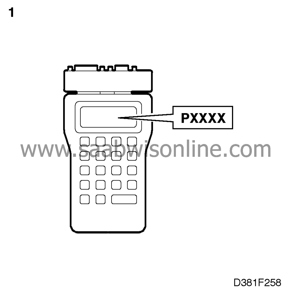
Always begin by using an ISAT Scan Tool to read the diagnostic trouble codes, if any. Use the "ALL SYSTEMS" command to obtain readouts of all diagnostic trouble codes. Make a note of the trouble codes or save them in the ISAT Scan Tool's internal memory by using the "SAVE FAULT CODES" command.
Internally stored diagnostic trouble codes can be read using the command "RECALL FAULT CODES".
Trouble codes present:
Continue with "Fault diagnosis with diagnostic trouble codes".
No diagnostic trouble codes present:
Continue with "Fault diagnosis, components".
|
|
2.
|
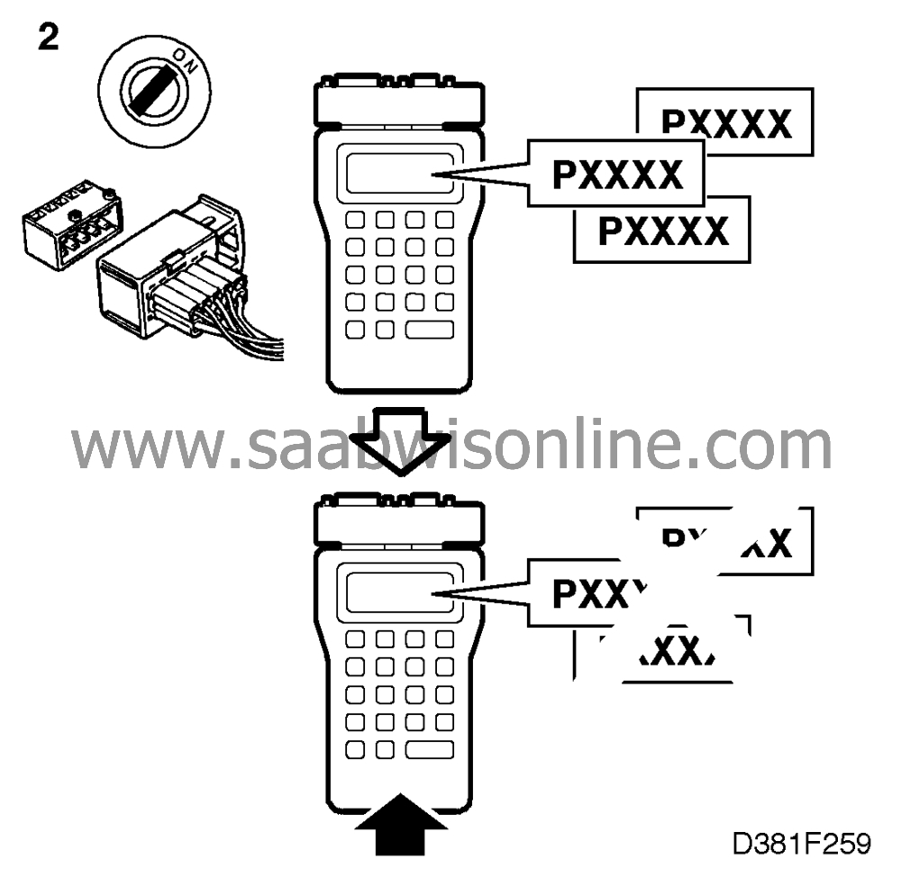
Some fault diagnosis procedures involve unplugging connectors while the ignition switch is in the ON position. This can give rise to diagnostic trouble codes. Therefore, when you have finished fault diagnosis, always clear any diagnostic trouble codes that may have been generated. Clear all diagnostic trouble codes by using the "CLEAR" command.
|
|
3.
|
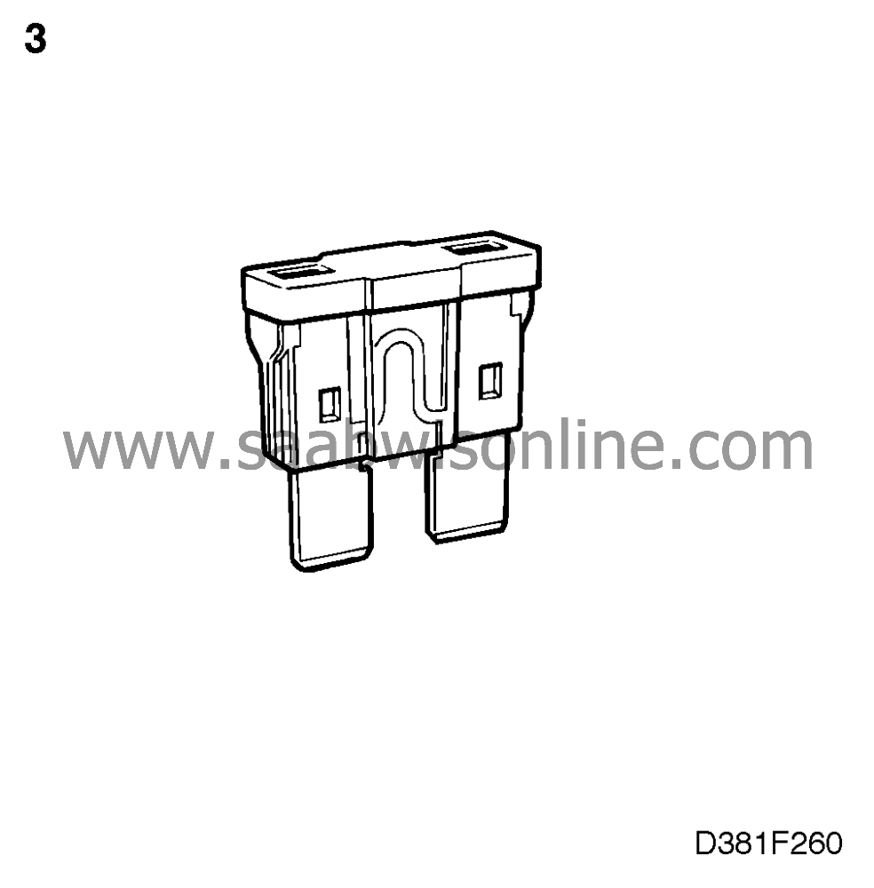
Check fuses 13, 17, 18, 30 and 34.
|
|
4.
|
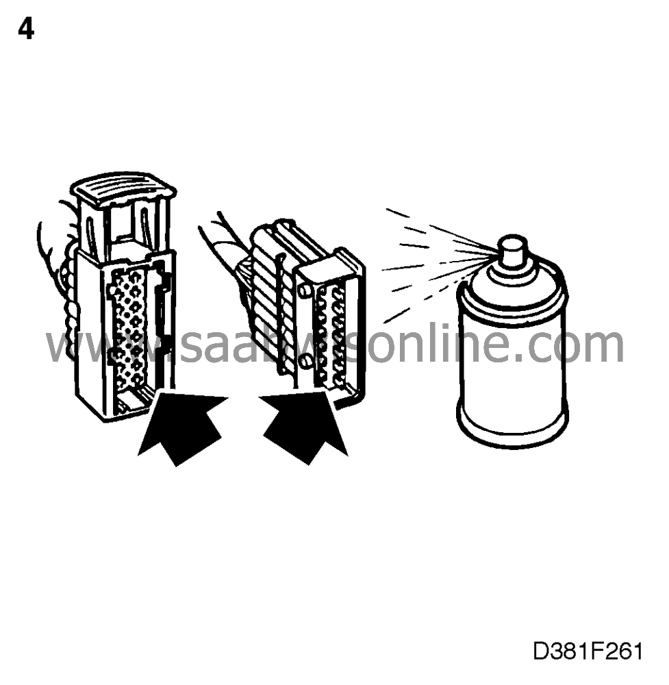
Check connectors and contacts, especially with respect to oxidized pins, looseness, extracted pins or other causes of bad contact. If contact problems are suspected, always use contact spray KONTAKT 61 (part no. 45-30 04 520) on the female connectors.
|
|
5.
|
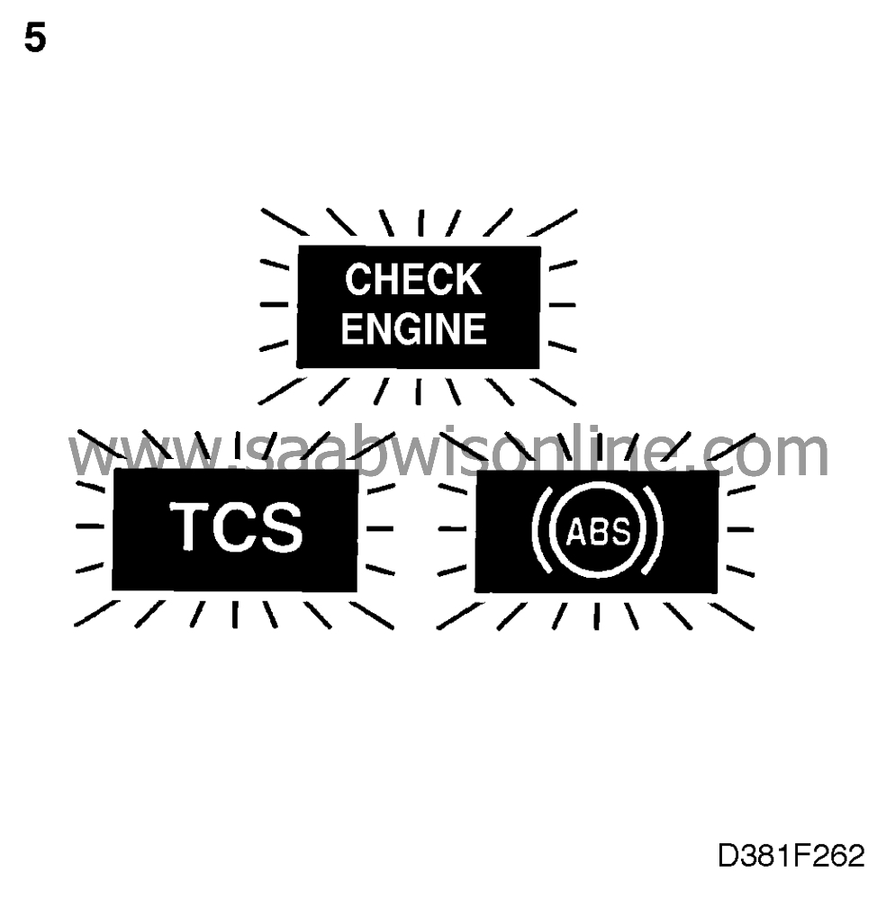
Check whether the CHECK ENGINE lamp (MIL) or any other warning lamp is on.
|
|
6.
|
Faults may be permanent or intermittent.
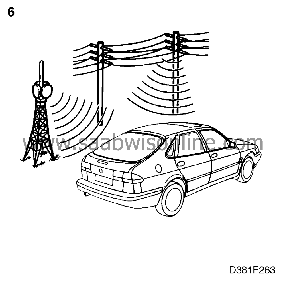
A constant fault displays continuous fault criteria, i.e. the fault exists only under certain conditions. Examples of such conditions are:
|
|
|
•
|
Faulty connectors (see point 4).
|
|
|
•
|
Electromagnetic interference. Interference may consist of electromagnetic radiation emanating from the car's own equipment or from powerful broadcasting transmitters when the car is driven past radio and TV masts, high-tension transmission lines and places like airports, etc.
|
|
|
•
|
Defective components. Poor contact in relays, solenoids, etc. can give rise to interference through sparking and arcing.
Intermittent faults call for careful analysis to avoid the replacement of components that are in perfect working order,
|
|
7.
|
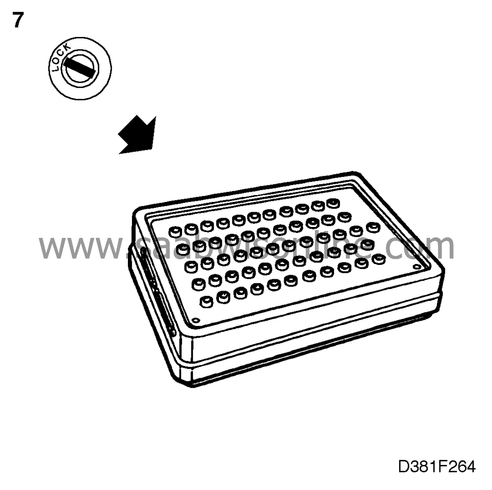
In general:
|
|
|
•
|
When connecting a BOB, make sure that the ignition switch is in the OFF position.
|
|
|
•
|
When unplugging connectors, make sure that the ignition switch is in the OFF position.
|
|
|
•
|
When taking resistance readings, make sure that the ignition switch is in the OFF position.
|
|
8.
|
Measuring the resistance of solenoids/relays. Nominal resistance is specified at 20
°
C (68
°
F). The resistance of the windings is extremely temperature-dependent and increases with rising temperature.
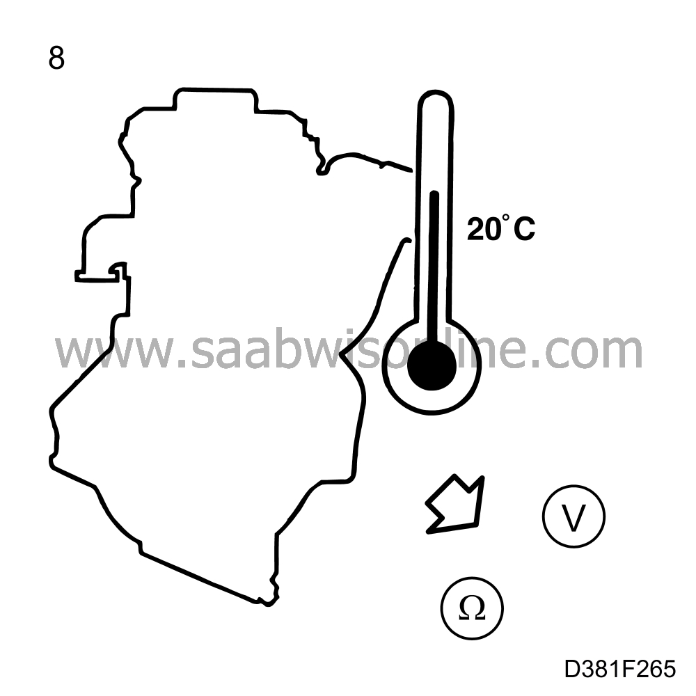
Exercise caution when judging the results of such resistance measurements.
|
|
9.
|
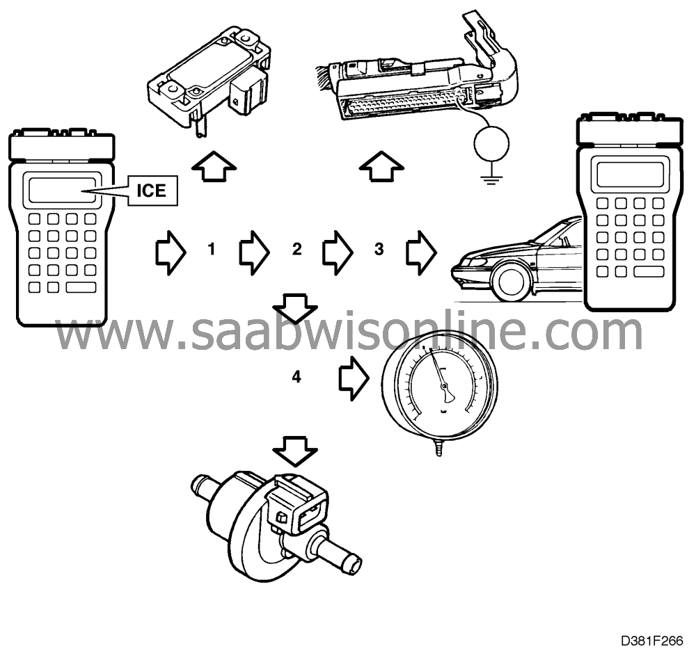
Fault diagnosis strategy, with or without diagnostic trouble codes, is based on the occurrence of one fault only - the primary fault. However, such a fault may give rise to other faults - consequential faults. If the primary fault is rectified, then the symptoms of the consequential faults will disappear at the same time. The probability of two faults occurring independently is considered to be slight and is not dealt with in this manual.
|
|
10.
|
Always end fault diagnosis, with or without diagnostic trouble codes, by checking that the fault symptoms do not persist and that the trouble codes do not recur after remedial action has been taken.
|


