Diagnostic tool communication, check
Symptom: Communication between the diagnostic tool and the control module cannot be established.
| Diagnostic tool communication, check |
Fault symptoms
Communication between the diagnostic tool and the control module cannot be established.Diagnostic procedure
1 Check the diagnostic tool connection
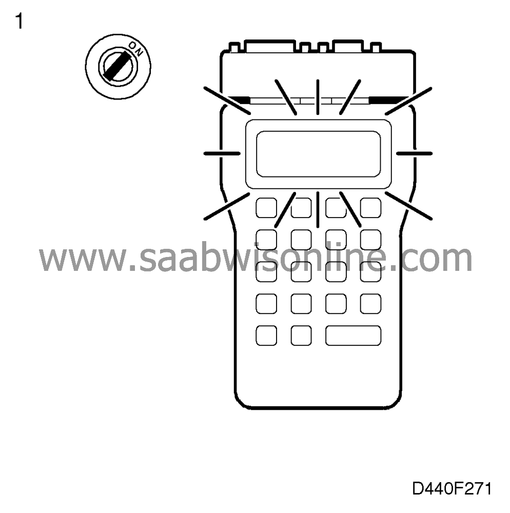
Connect the diagnostic tool to the car's data link connector.
Does the diagnostic tool display go on?
| yes |
Proceed to point 4.
| no |
Check that fuse 13 is intact and continue with point 2.
2 Check the current (+30 circuit) supplied to the data link connector.
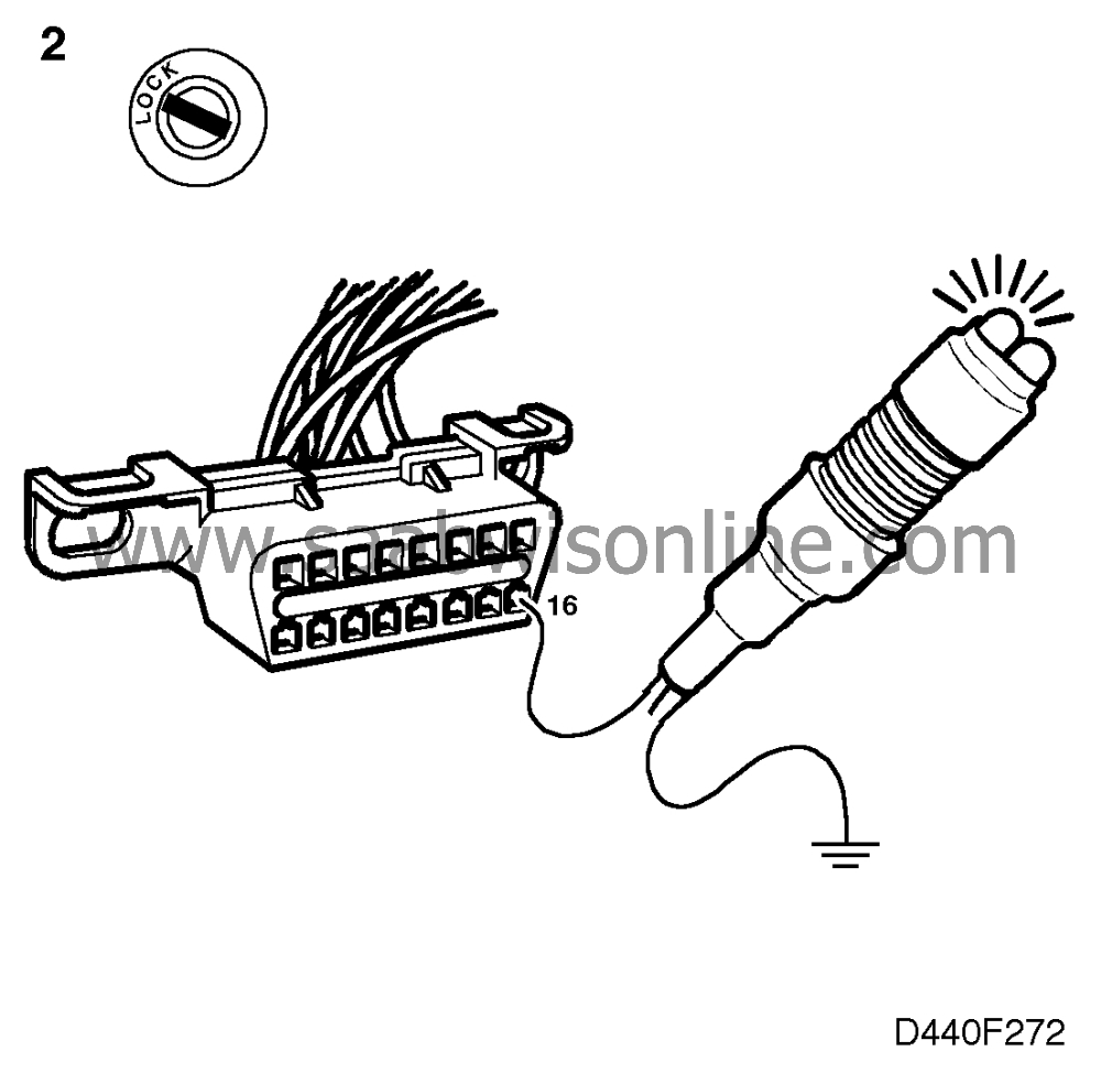
Connect a test lamp to pin 16 of the data link connector and a good grounding point. The test lamp should light up if current (+30 circuit) is present.
Did the lamp light up?
| yes |
Continue with step 3.
| no |
Check and, if necessary, rectify the wiring between pin 16 and fuse 13. If the wiring is OK, continue fault diagnosis as described in the "+30 power supply" section of Service Manual 3:2 "Electrical system, wiring diagrams".
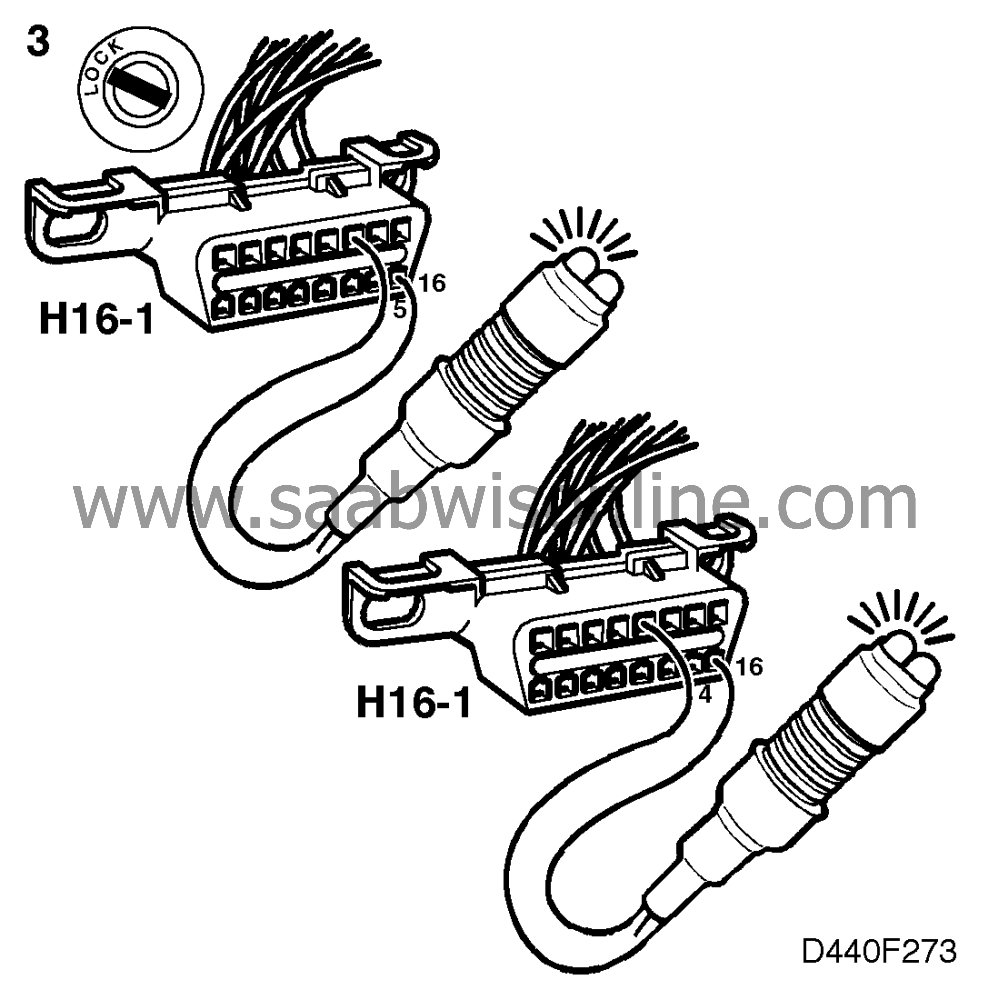
3 Check the ground connection in the data link connector.
| - |
Connect a test lamp to pins 5 and 16 of the data link connector.
|
|
| - |
Connect a test lamp to pins 4 and 16 of the data link connector. In both cases the test lamp should light up if there is a connection to ground.
|
|
Did the lamp light up?
| yes |
Check the diagnostic tool.
| no |
Repair or replace the wiring between pin 5 and grounding point G33S or else between pin 4 and grounding point G33P (LHD) or G34P (RHD).
4 Checking diagnostic tool contact with gearbox
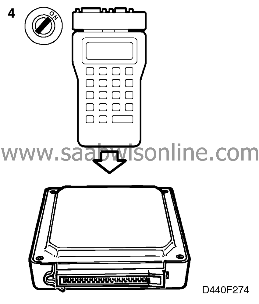
Select "AUT TRANSMISSION". The diagnostic tool should then display the menu for the gearbox, see
 .
.
Is the menu displayed?
| yes |
Continue with step 7.
| no |
Continue with point 5.
5 Checking the diagnostic tool contact with other systems
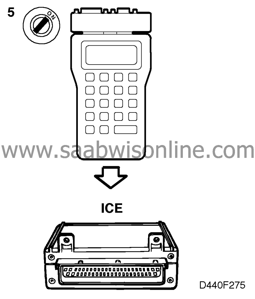
Select another system in the car, ICE for instance. The diagnostic tool should display the menu for that system.
Is the menu displayed?
| yes |
Continue with step 6.
| no |
Check the diagnostic tool.
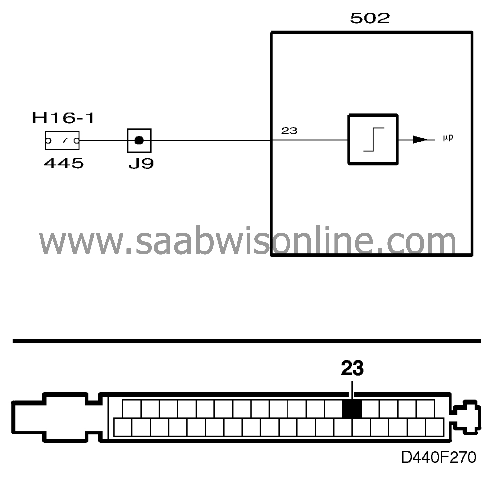
6 Check the wiring harness
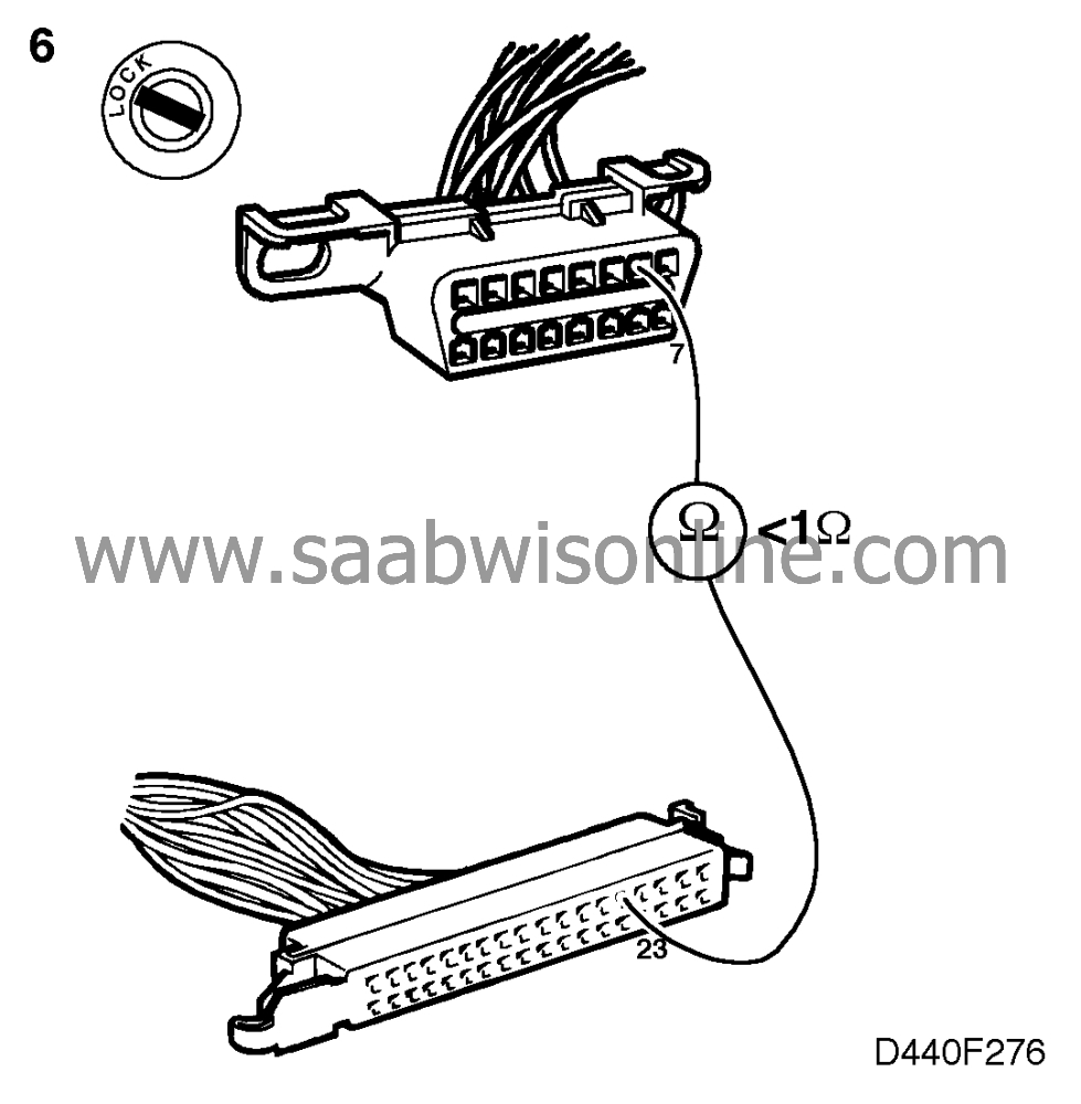
Check the continuity of the wiring harness between pin 7 of the data link connector and pin 23 of the transmission control module. The resistance should be <1 ohm.
Is the resistance correct?
| yes |
Continue with step 7.
| no |
Repair or replace the wiring harness and continue with point 7.
7 Final check
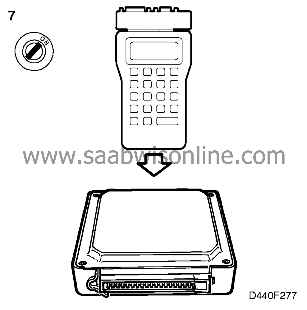
Select "AUT TRANSMISSION". The diagnostic tool should now display the menu for the automatic transmission.
Is the menu displayed?
| yes |
The remedial action taken was correct.
| no |
Continue with
.
This project is supported by memberships and donations. If you use this site, please consider Joining SCNA and/or making a donation.
Our Friends
