To dismantle
| To dismantle |
| • |
remove the reversing-light switch to prevent it being damaged and cover the hole left by the switch.
|
|
| 1. |
Fit the gearbox in a work fixture with holder 87 92 228
 .
.
|
|
| 2. |
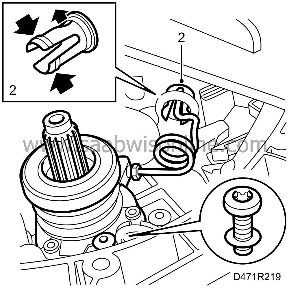
Hydraulic clutch: Detach the delivery line. Compress the sleeve on the inside, using a pair of pliers, and push the delivery line forward. Prise up the catch on the sleeve and press in the delivery line to detach it.
|
|
| 3. |
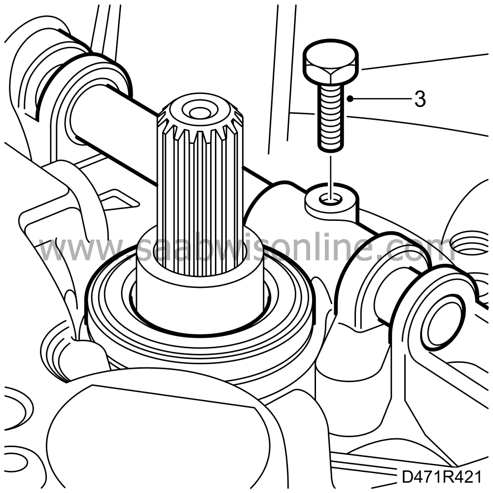
Mechanical clutch: Remove the screw from the fork for the clutch release bearing.
|
|
| 4. |
|
|
| 5. |
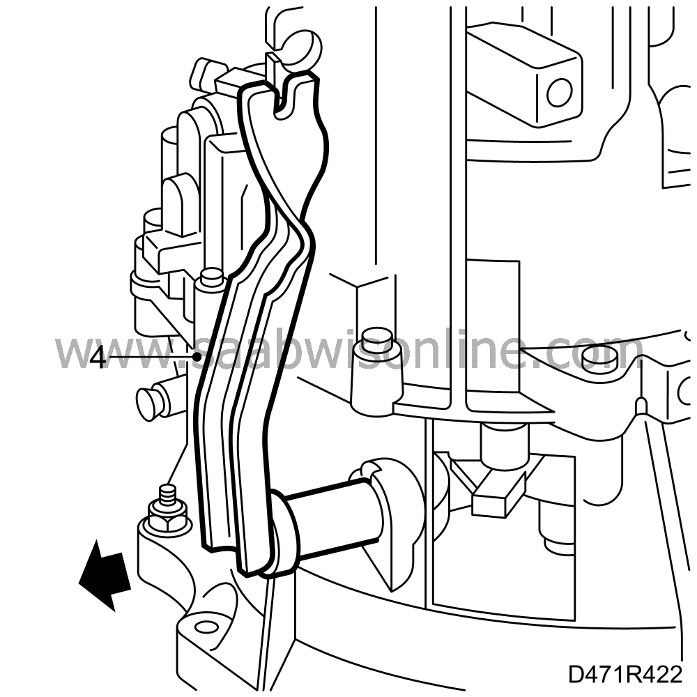
Undo the slave cylinder screws and remove it.
|
|
| 6. |
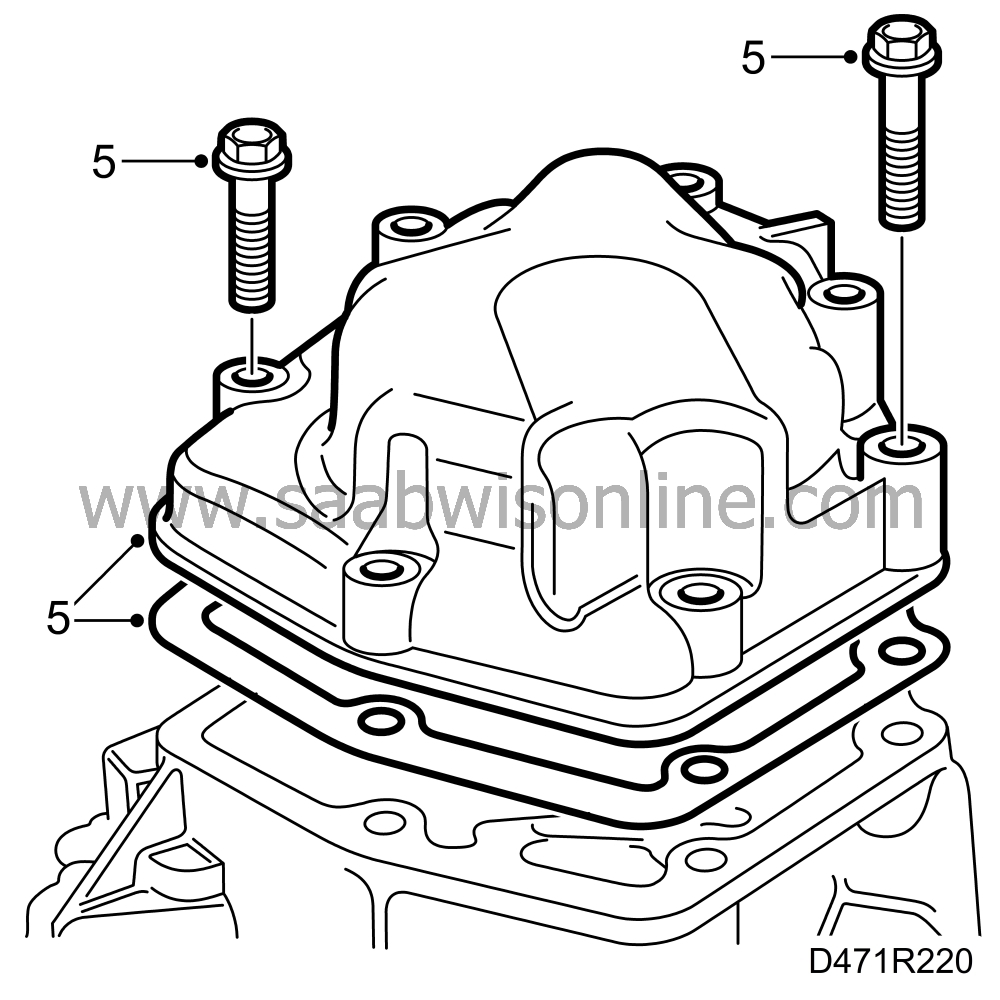
Unscrew the bolt for the reverse shaft. Note the O-ring. This applies to gearbox number N94146 and later. Unbolt the end cover. Remove the cover and gasket.
|
|
| 7. |
Engage 1st gear to secure the gearbox and prevent the selector mechanism detent balls from coming out. Tap out the retention pin for the 5th gear selector fork.

Remove the fork and synchromesh sleeve and then refit the synchromesh sleeve. |
||||||||||
| 8. |
Press down the synchromesh sleeve so that 5th gear is engaged. Two gears must be engaged simultaneously when the nut on the output shaft is unscrewed.
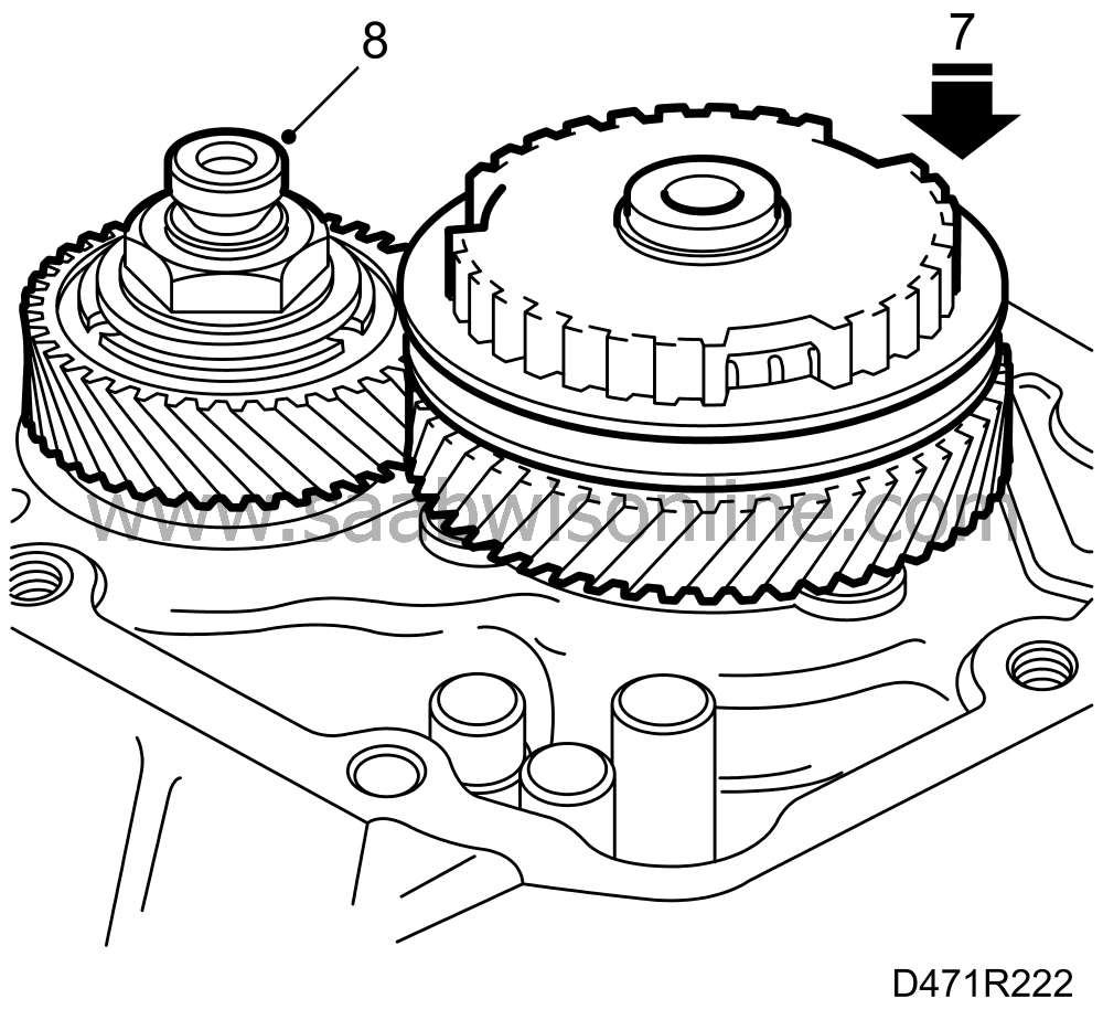
Note that the synchromesh sleeve may only be placed on the synchromesh hub when the high lugs on the sleeve are opposite the tooth gaps on the synchromesh hub that are opposite the deep tooth gaps. |
|
| 9. |
Tap off the lock on the output shaft nut using a drift.
Remove the nut.
|
||||||||||
| 10. |
Remove the circlip for 5th gear synchromesh hub. This is made easier by first carefully tapping down the hub.

Lift off the synchromesh sleeve and then use puller 87 91 287
|
|
| 11. |
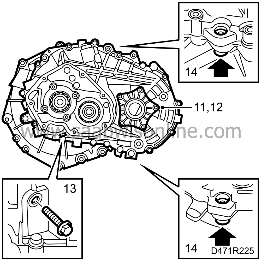
Remove the gear wheel for 5th gear with puller 89 96 084
 , puller 87 92 566
 and sleeve 87 91 410
 .
.

|
|
| 12. |
Undo the screws for the differential seal retainer.
|
|
| 13. |
Remove the seal retainer and keep the shims.
|
|
| 14. |
Undo the screw for the reverse shaft support in the gearcase.
|
|
| 15. |
Undo and remove the bolts from the mating surface between the gearcase and the clutch housing. Tap down the 2 locating sleeves.
|
|
| 16. |
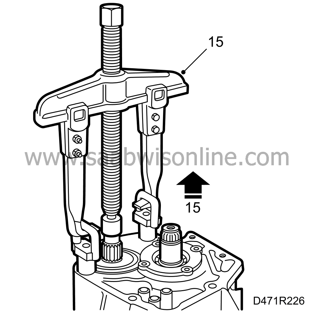
Check that a gear is engaged. This will prevent the input and output shafts from coming out at the same time. Screw in the two lifting eyes 87 92 129
 . Fit sleeve 87 91 410
 on the end of the output shaft. Hook puller 87 91 287 with arms 87 91 303
 in the tools and carefully pull out the casing until pinion and bearing come off the shaft. Tap carefully so that the mating faces separate.
|
|
| 17. |
Remove tools. Lift off the gearcase.
|
|
| 18. |
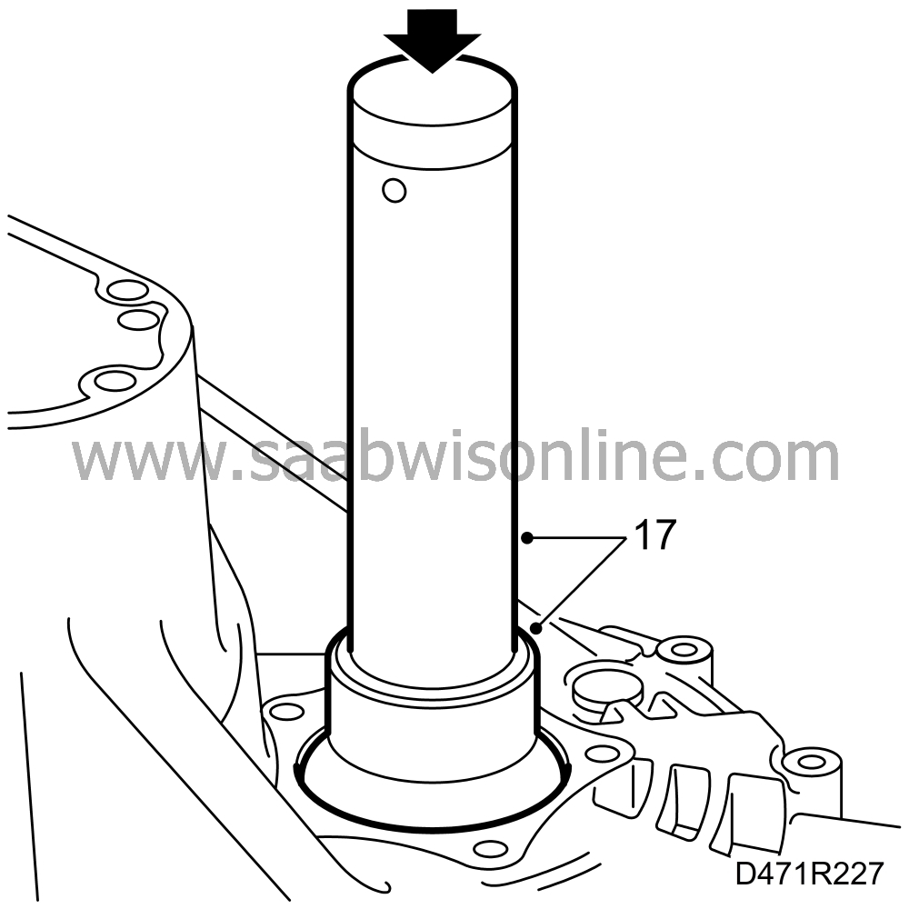
Tap out the differential bearing race. Use sleeve 87 92 202
 .
.
|
|
| 19. |
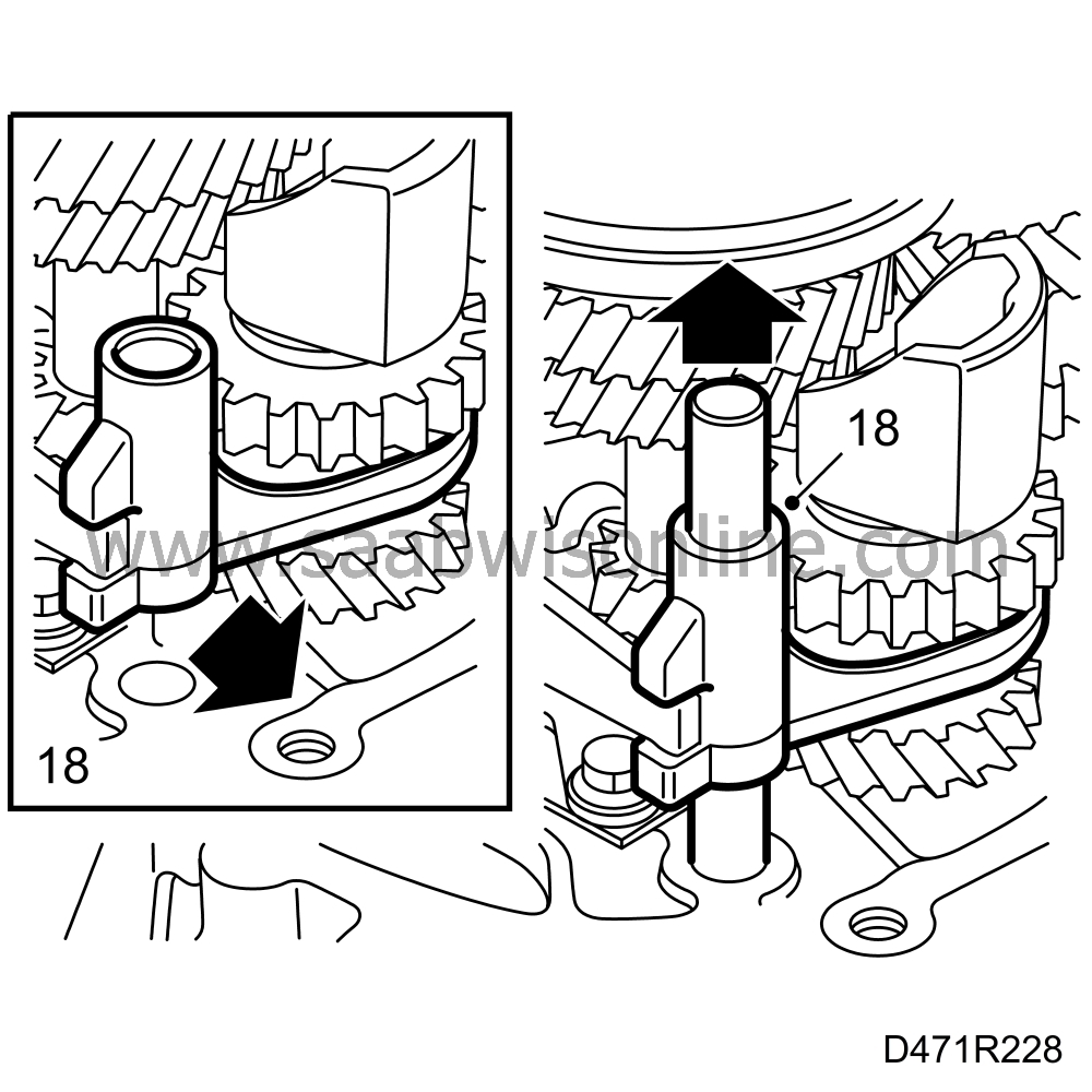
Remove shaft and selector fork for reverse.
|
|
| 20. |
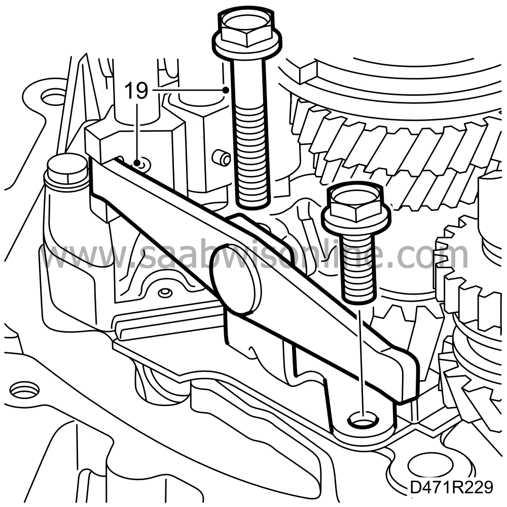
Unscrew and remove the reverse gear selector fork.
|
|
| 21. |
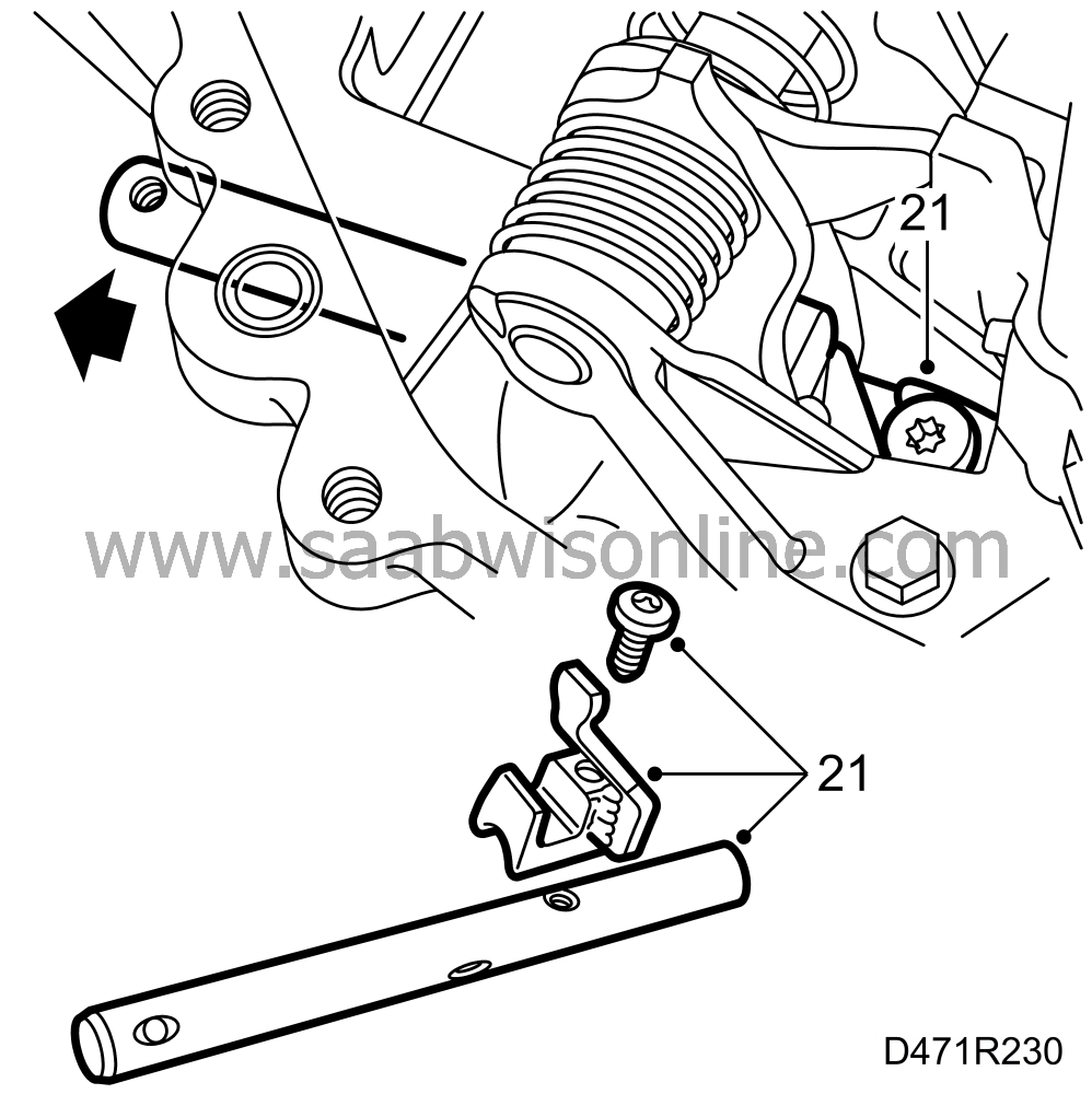
Engage reverse gear on the selector mechanism to gain access to the screw for the selector rod.
|
|
| 22. |
Remove the screw for the driver on the selector rod. Withdraw the shaft and keep the driver.
|
|
| 23. |
Disengage reverse. Remove the screw and lift the selector mechanism slightly to lift the locating sleeves from their seats. Lift off the sleeves.

Pull the selector mechanism back towards the differential and angle it out slightly. Lift out the selector mechanism. |
|
| 24. |
Lift the input shaft slightly and lift the reverse shaft and pinion (reverse gear).

|
|
| 25. |
Lift off the 4th gear wheel, clamping sleeve and spacer sleeve.

|
|
| 26. |
Fit puller 87 91 287
 with puller arms 87 91 295
 under the 1st gear wheel on the output shaft. Lift up the drive assembly using two screwdrivers so that the puller arms can go in under the 1st gear pinion. Fit sleeve 87 91 410
 as protection on the end of the output shaft. Pull slightly and fit assembly fixture 87 92 103
 that holds the 1st and 2nd gear synchromesh assembly together. Fit a cable tie round the tools and drive assembly. Pull up all gears about 15 mm on the output shaft.

|
|
| 27. |
Lift out the input shaft.
|
|
| 28. |
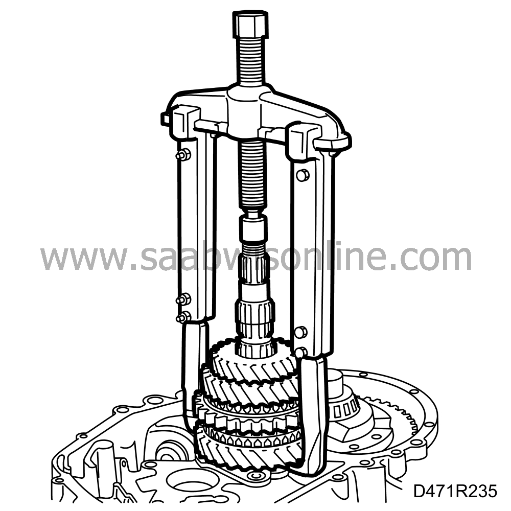
Tighten until the gear wheels on the output shaft become detached.
|
|
| 29. |
Lift off the gear wheels (for 1st, 2nd and 3rd gear) as well as baulk rings and synchromesh sleeve, held together by assembly fixture 87 92 103
 .
.
|
|
| 30. |
Undo 4 bolts and remove the output shaft bearing support.

|
|||||||
| 31. |
Pull up the output shaft. Use support 87 91 188
 , driver 87 91 428
 and puller 87 91 261
 .
.

|
|
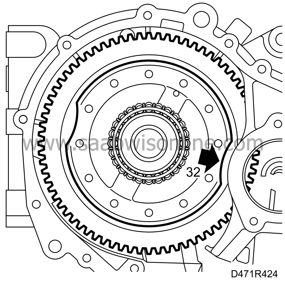
| 32. |
Lift out the differential.
|
|
| 33. |
If the differential has a socket as shown in the figure, arrange this so that it faces the bulge by the output shaft's bearing support and lift out the differential.
|
|


