Basic design
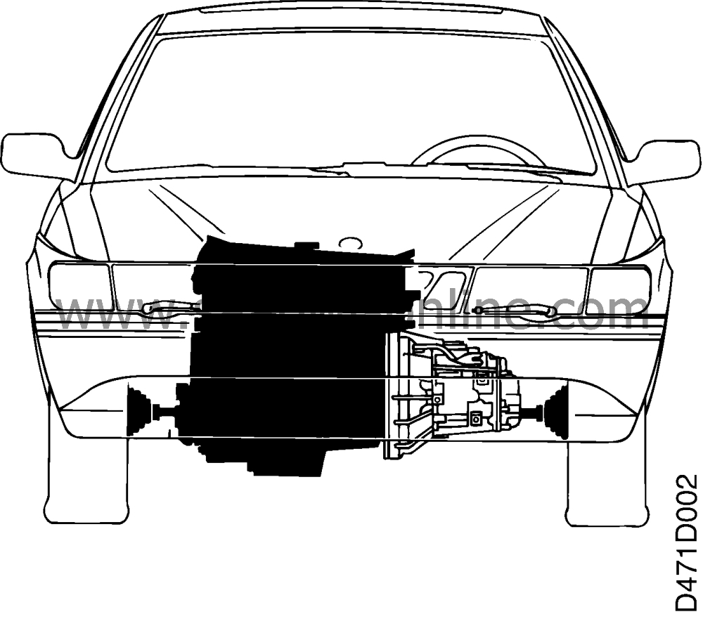
The gearbox is designed for front wheel drive and forms a unit with the engine. The drive unit is transversely mounted in the car, which gives good cooling and the shortest possible route for the transfer of power to the drive wheels.

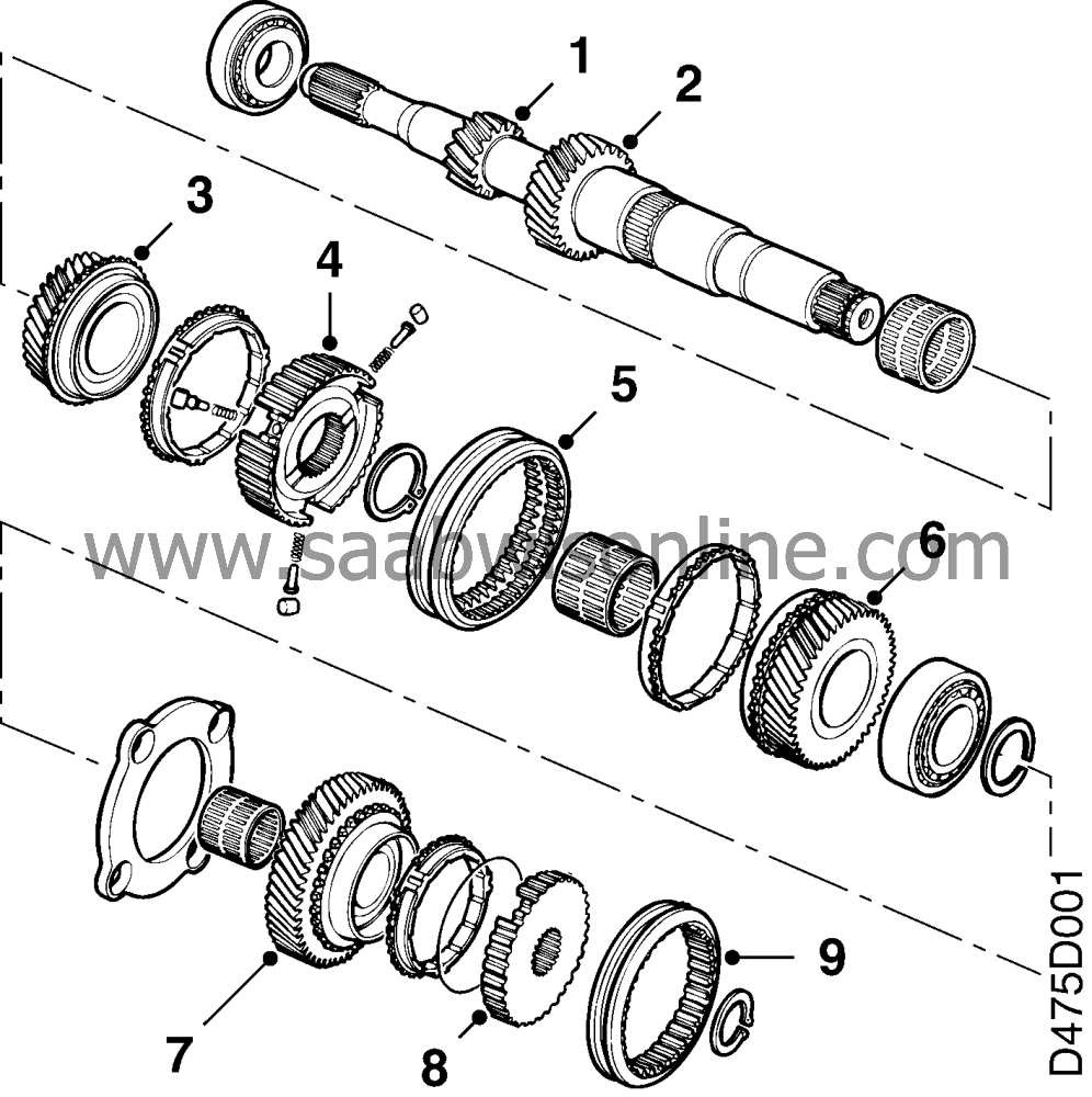
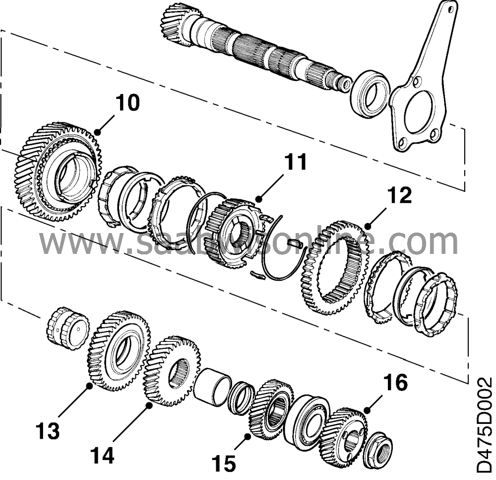
The manual gearbox is a five-speed gearbox. All gears (including reverse) are synchronized. The gearbox has relatively small rotating masses, and thus small moments of inertia to be braked at each gear change. This makes gear- changing easy and smooth and interior wear on baulk rings and sleeves almost non-existent. The baulk rings are placed on the input and output shafts.

Input shaft - Output shaft - Reversing shaft
|
9.
|
Synchromesh sleeve, 5th
|
Input and output shafts are fitted with taper roller bearings to obtain maximum flexural rigidity in the shafts under load. The output shaft's roller bearing is placed inside the final drive gear, which gives the shaft maximum insensitivity to high loads.

Output shaft

Reverse shaft
Note that the gears on the input shaft are called
pinions
(are driving), while the gears on the output shaft are called
gear wheels
(are driven). The 3rd, 4th and 5th gear pinions are fitted in needle bearings in order to achieve the lowest possible losses from friction and thus a high degree of efficiency.
The gear box has only two parting lines. The parting surface between clutch case and gear case is sealed with sealant and the parting surface between gear case and end cover is sealed with a gasket. Ventilation and de-airing are carried out through a “labyrinth” in the upper part of the gear case, in which there is also a filter (sintered plug) to keep out dirt and moisture.

Gearbox mating face


