B1228, cars with central warning lamp
|
|
B1228, cars with central warning lamp
|
Bulb for SRS symbol, broken, open circuit in the wiring harness or short-circuit to ground.
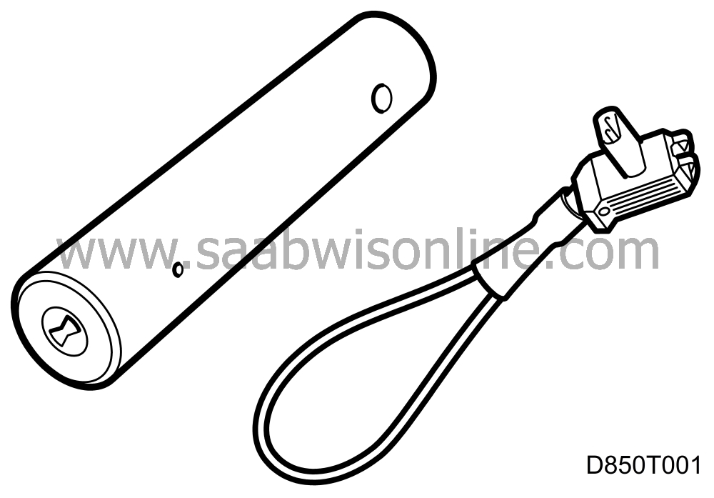
The reference resistor is available in two versions. A newer, part no. 86 12 095
 , and an older, part no. 84 71 153
 . The new type has closer tolerance limits and should be used for more reliable diagnosis. The illustrations in the following chapter show the older type of reference resistor.
The bulb is connected to pin 7 on the control module.
Diagnostic procedure
|
1.
|
Connect the diagnostic tool. Note the diagnostic trouble code and type of fault.
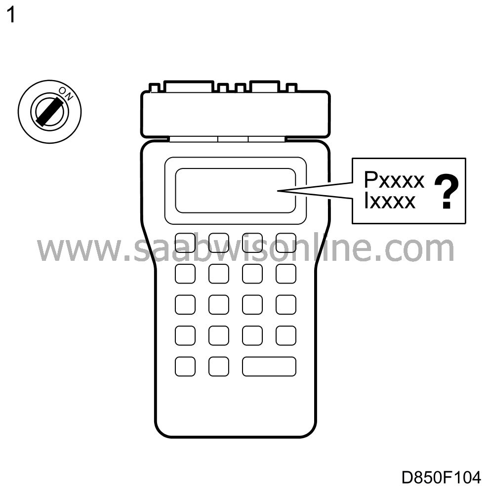
P=permanent fault, I=intermittent fault.
If the fault is permanent:
Go to point 3.
If the fault is intermittent:
Go to point 2.
|
|
2.
|
The fault is intermittent. Try to provoke the fault at each test section in the continued fault diagnosis.
Move the connectors and cables and turn the steering wheel while testing.
Go to point 3.
|
|
3.
|
Turn on the ignition and check the SRS lamp. Then choose the correct fault diagnosis below.
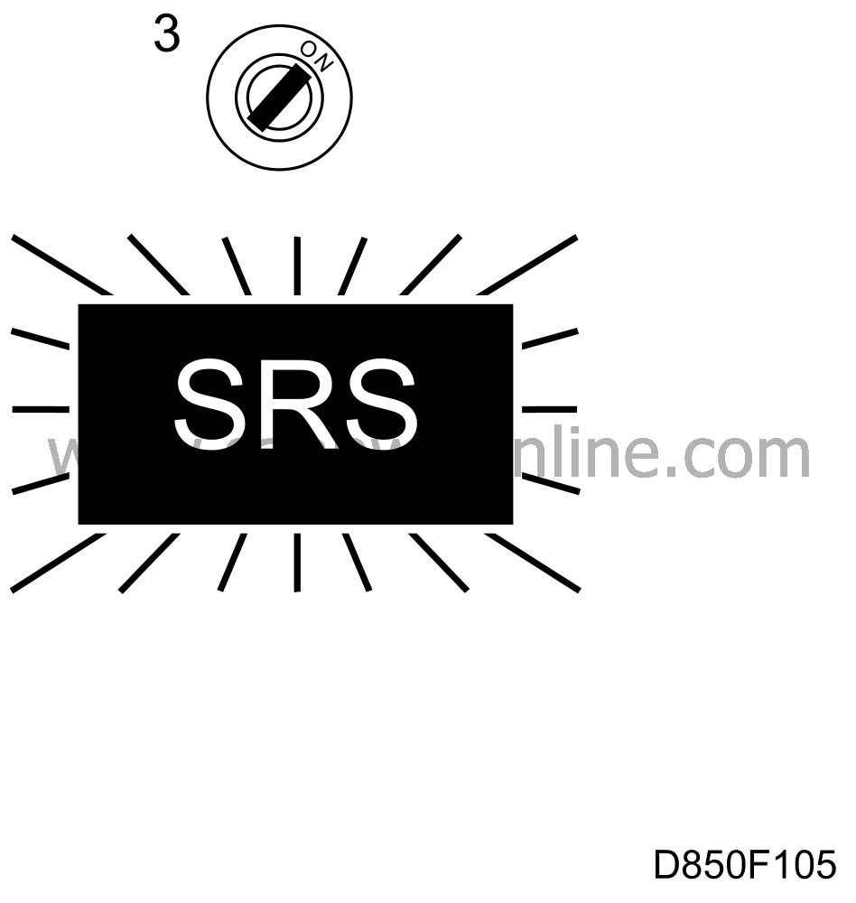
The lamp should go on for 3-4 seconds after the ignition has been turned on.
The SRS lamp does not come on:
Go to point 4.
The SRS lamp shines continuously:
Go to point 7.
|
|
4.
|
Expose the main instrument unit and replace the SRS bulb. Turn on the ignition.
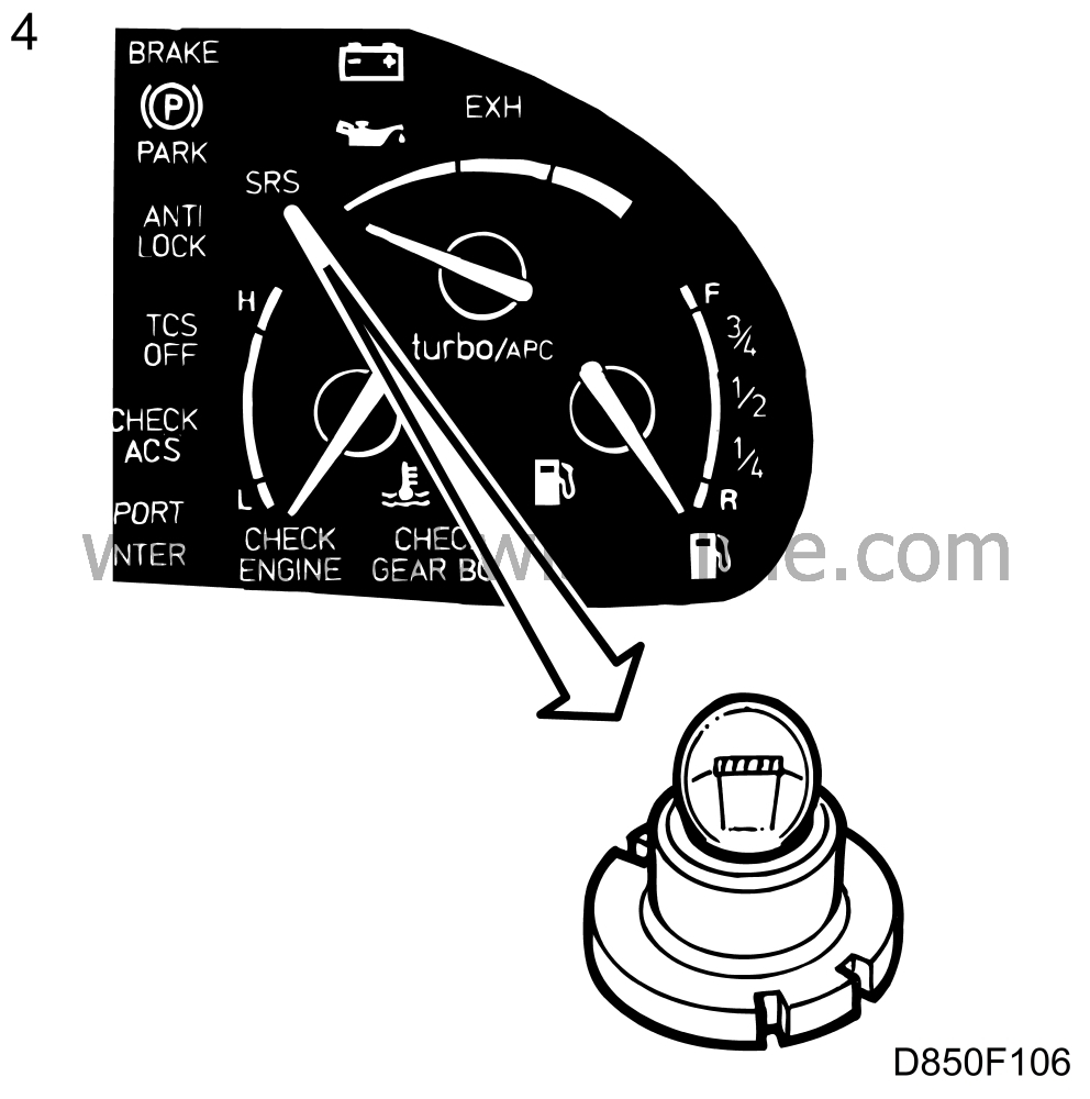
The lamp should go on for 3-4 seconds after the ignition has been turned on.
If the lamp comes on.
The fault was in the lamp. Go to point 11.
If the lamp does not come on:
Go to point 5.
|
|
5.
|
Turn off the ignition and remove the negative cable from the battery. Undo the bolts securing the steering wheel airbag. Unplug the connector from the back of the airbag and connect the reference resistor 84 71 153 to the connector.
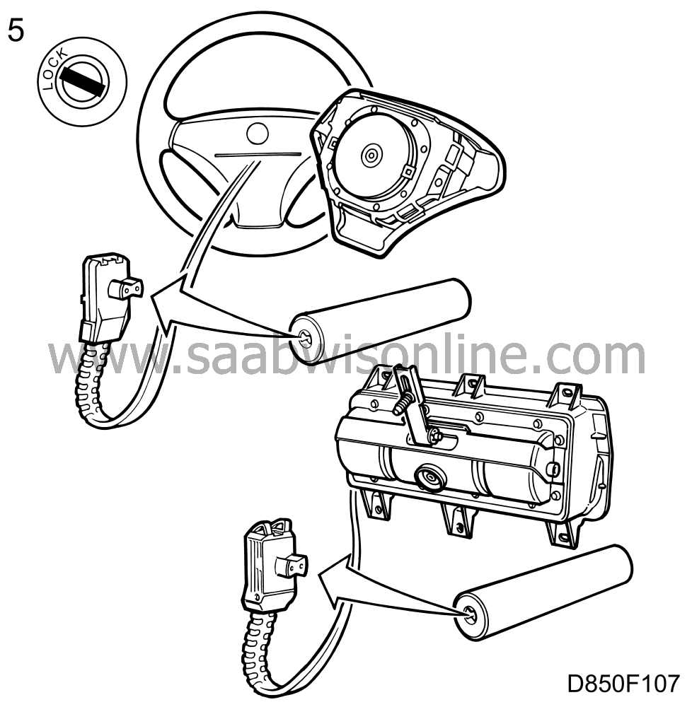
On cars with airbag on passenger side;
|
|
|
5.a.
|
Remove the glove-box and unplug the connector on the back of the passenger airbag.
|
|
|
5.b.
|
Connect the reference resistor 84 71 153 to the connector.
Go to point 6.
|
|
6.
|
Expose the SRS control module. Unplug the SRS control module connector and connect a BOB to the wiring harness.
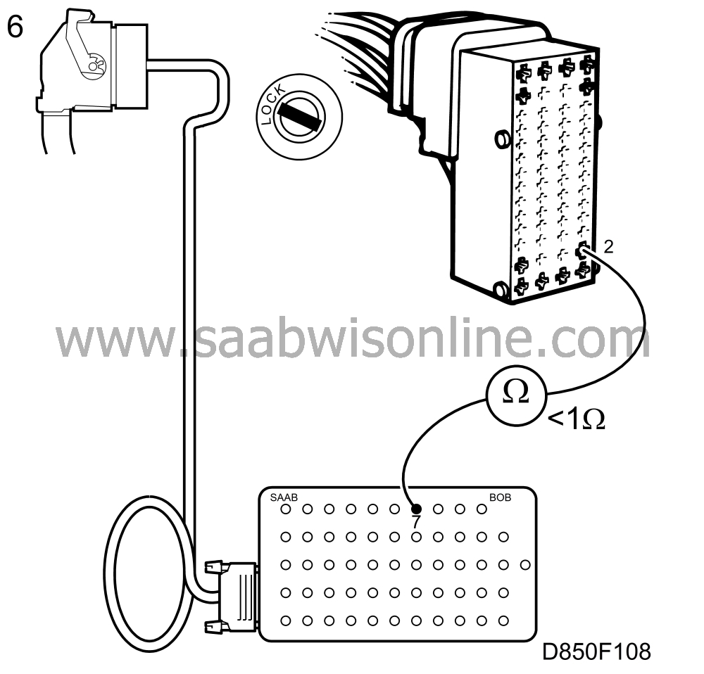
Expose the main instrument unit. Unplug the connector from the main instrument unit.
Connect an ohmmeter between sleeve 2 in the main instrument unit connector on the wiring harness and connection 7 on the BOB. The ohmmeter should read less than 1 ohm.
If the value is OK:
Go to section: Procedure for replacing the control module
 .
.
If the value differs:
Check the cable between sleeve 2 in the main instrument unit connector and sleeve 7 in the control module connector for open circuits/loose connections.
Rectify the fault and go to point 11.
|
|
7.
|
Turn off the ignition and remove the negative cable from the battery. Undo the bolts securing the steering wheel airbag. Unplug the connector from the back of the airbag and connect the reference resistor 84 71 153 to the connector.
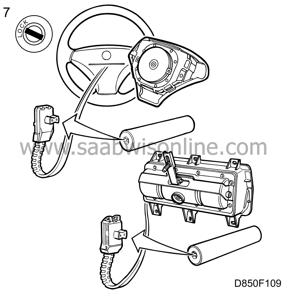
On cars with airbag on passenger side;
|
|
|
7.a.
|
Remove the glove-box and unplug the connector on the back of the passenger airbag.
|
|
|
7.b.
|
Connect the reference resistor 84 71153 to the connector.
Go to point 8.
|
|
8.
|
Expose the SRS control module. Remove the connector from the SRS control module and connect a BOB to the wiring harness. Replace the negative cable on the battery and turn on the ignition.
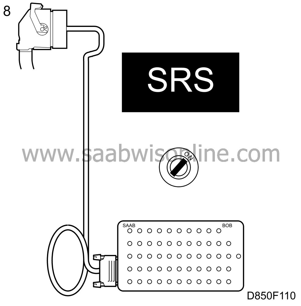
The SRS lamp should not come on.
If the lamp does not come on:
Go to point 11.
If the lamp comes on.
Go to point 9.
|
|
9.
|
Remove the SRS control module ground connection G4. The SRS lamp should go out.
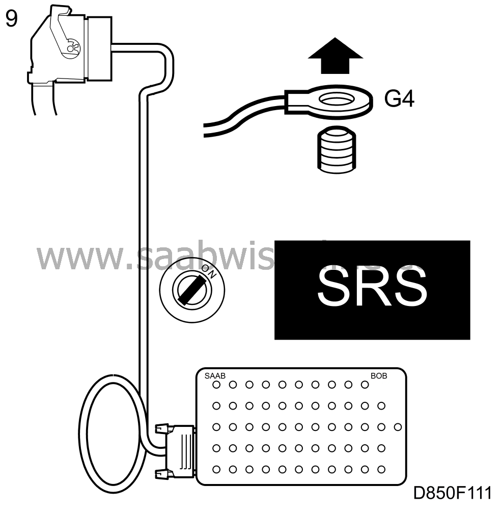
If the lamp goes out:
The fault lies in the control module. Change the wiring harness. Refit the ground connection and go to point 11.
If the lamp does not go out:
Refit the ground connection and go to point 10.
|
|
10.
|
Expose the main instrument unit.
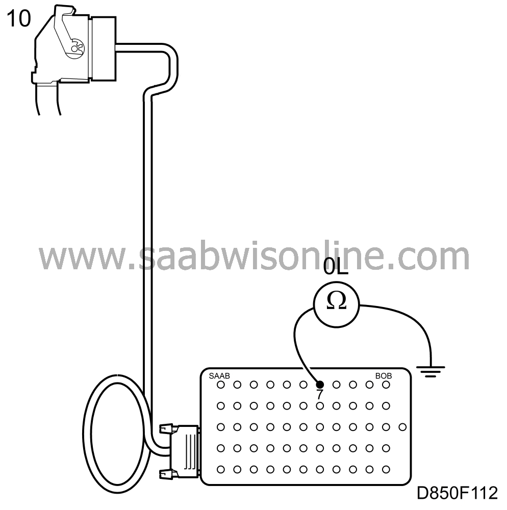
Unplug the main instrument unit connector. Connect an ohmmeter between connection 7 on BOB and a good grounding point.
The ohmmeter should indicate infinite resistance.
If the value is OK: Go to point 11. If the value differs: There is an overload to ground on the cable between the SRS control module connector and the main instrument unit connector. Locate the cause and rectify the fault. Then go to point 11.
|
|
11.
|
Turn off the ignition and remove the negative cable on the battery. Remove the reference resistor and connect all the connectors to their original components. Refit the negative cable on the battery and turn on the ignition. Clear the diagnostic trouble code.
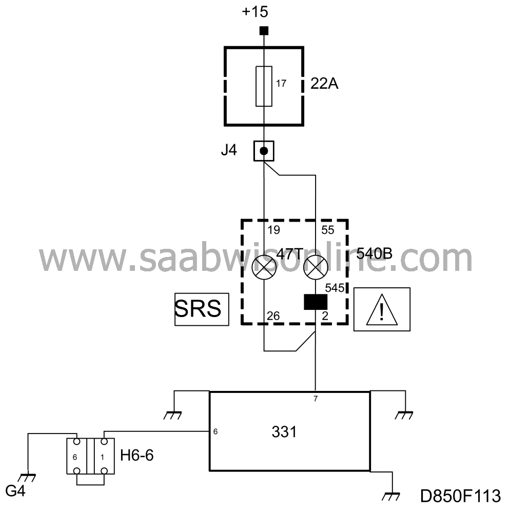
Turn off the ignition and turn it on again, wait for at least 10 seconds.
Check to see if the diagnostic trouble code returns.
If the diagnostic trouble code returns:
Go to section: Procedure for replacing the control module

If the diagnostic trouble code does not return:
Restore the car.
|
 , and an older, part no. 84 71 153
 . The new type has closer tolerance limits and should be used for more reliable diagnosis. The illustrations in the following chapter show the older type of reference resistor.


