(210-2561 utg. 3) Noise from the timing chain and oil sludge in the engine
Symptom: Rattling timing chain, abnormal whining, bellowing or knocking noise from the engine or oil pressure lamp on.
|
TECHNICAL SERVICE BULLETIN
|
|
Bulletin Nbr:
|
210-2561 utg. 3
|
|
Date:
...........
|
April 2006
|
|
Market:
|
ej US/CA
|
|
|
Noise from the timing chain and oil sludge in the engine
|
Saab 9-5 M98-03 with engine alternative B205 and B235
Saab 9-3 (9400) M99-03 with engine alternative B205 and B235
Various conditions can cause the formation of oil sludge in the engine or a rattling noise from the timing chain and balancer shaft chain.
In the case of customer complaint, the following procedure must be carried out.
|
Note
|
|
If repair is to be carried out under New Car Warranty or Special Policy, prior authorisation from is required from the manager responsible at the importer, ETAC or CIC.
|
Symptom description
Rattling timing chain, abnormal whining, bellowing or knocking noise from the engine or oil pressure lamp on.
55 561 200 Renovation kit, crankcase ventilation
For any other parts required, see EPC
Replace if necessary:
91 86 156 Oil suction pipe/strainer
91 38 009 O-ring
55 560 445 Hose to oil pan
55 560 463 Hose to camshaft cover
93 99 973 Hose with check valve
For any other parts required, see EPC
|
Action, checking the damage
|
|
1.
|
Checking
Check the oil level, fill as necessary. If more than 1 litre of oil is added then run the engine for 15 minutes more before checking for noise.
Listen to the engine for noise. The engine must be run to operating temperature! If the engine sounds normal and the oil pressure lamp does not come on, consult with the owner about the need to perform more frequent oil and filter changes and the need to switch to fully synthetic oil in accordance with Saab recommendations.
|
|
2.
|
If the oil pressure lamp flashes or comes on steadily:
|
|
|
2.a.
|
Check the oil level, top up as necessary.
|
|
|
2.b.
|
Check the oil pressure in accordance with WIS - Engine - Basic engine 4-cyl (petrol) - Adjustment/Replacement - Measuring oil pressure. If the oil pressure is in accordance with the specification, replace the oil pressure sensor. If not, continue with step 5.
|
|
3.
|
Checking in the event of noise:
|
|
|
3.a.
|
Checking in the event of noise.
|
|
|
3.b.
|
If a high-pitched whining noise is audible, particularly in a cold engine, then it is most often from the oil filter or the check valve in the oil filter adapter.
|
|
|
3.c.
|
If a low-pitched "bellowing" noise is audible at idling speed, similar to the noise from a hydraulic pump, then this indicates a clogged oil strainer.
|
|
|
3.d.
|
If a knocking noise can be heard from the lower end of the engine then this indicates noise from the bearings.
|
|
|
3.e.
|
If any of the above noises can be heard, proceed to step 5.
|
|
|
3.f.
|
If noise is coming from the timing chain or balancer shaft chain, continue with step 4.
|
|
4.
|
Checking wear on timing and balancer shaft chains:
|
|
|
4.a.
|
Remove the small hex bolt from the end of the tensioner so that the piston does not protrude further when the tensioner is removed. See WIS - Engine - Basic engine 4-cyl (petrol) - Adjustment/Replacement - Chain tensioner, timing chain.
|
|
|
4.b.
|
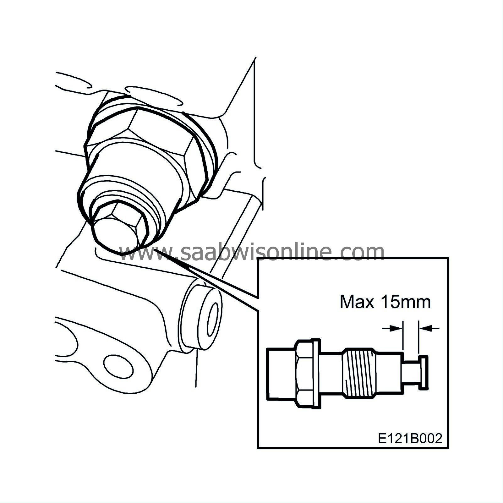
Remove the tensioner from the cylinder block and measure the length, see illustration.
|
|
|
4.c.
|
If the piston in the tensioner protrudes less than 15 mm, continue with step 5.
|
|
|
4.d.
|
If the tensioner piston protrudes more than 15 mm, then both the timing and balancer shaft chains must be replaced.
|
Note
|
|
Before proceeding with chain replacement, any other damage must be identified. Continue with step 5.
|
9-5:
See TSB 210-2480 edition 2.
9-3 (9400):
See WIS - Engine - Basic Engine - Adjustment/Replacement - Changing the balancer shaft chain B235 and B205.
|
|
5.
|
Determining the extent of damage to engine lower end:
|
|
|
5.a.
|
Remove the pan. See WIS - Engine - Basic engine - Adjustment/Replacement - Oil sump (in car)
|
|
|
5.b.
|
Remove the big-end bearings on cylinders 1 and 4.
|
|
|
5.c.
|
Add a bead of 30 06 558 Plastigauge. Type PG-1 (green) must be used.
|
|
|
5.d.
|
Fit the bearing caps with bearing shells (the marking figures on the connecting rods turned to the same direction).
Tightening torque, with nut 20 Nm +70
°
(15 lbf ft +70
°
)
Tightening torque, with screw 25 Nm +100
°
(18 lbf ft +100
°
)
|
|
|
5.e.
|
Remove the bearing caps and measure the Plastigauge strip. The bearing play must be between 0.014 - 0.062 mm.
|
|
|
5.f.
|
In the event of bearing damage, replace the short block, see WIS - Engine - Basic engine - Adjustment/Replacement - Powertrain. If the bearings are within the specification, continue with "Action, cleaning the engine components".
|
|
Action, cleaning the engine components
|
To ensure that the engine does not return with additional subsequent damage it is imperative that all components are cleaned before reassembly.
|
1.
|
Cylinder head:
If it is determined after inspection that the cylinder head must be cleaned to a higher level that could be achieved while installed in the car, then remove the cylinder head assembly for cleaning. See WIS - Engine - Basic engine 4-cyl - Adjustment/Replacement - Cylinder head.
|
|
|
1.a.
|
Remove the intake and exhaust manifolds and thermostat housing from the cylinder head.
|
|
|
1.b.
|
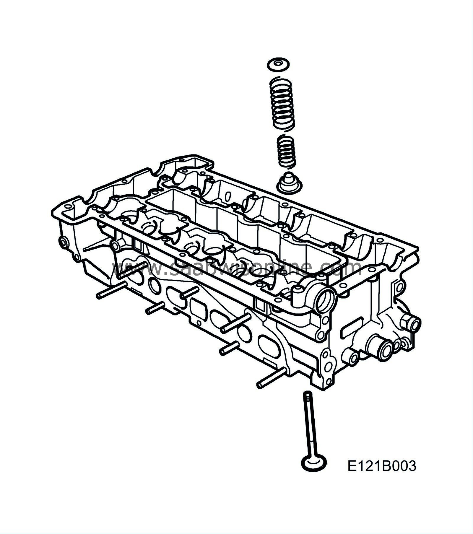
Remove the camshaft bearing caps, camshafts, tappets, valve springs, valves and valve seals.
|
|
|
1.c.
|
Refit the bearing caps loosely.
|
|
|
1.d.
|
Place the cylinder head with components (but not the tappets) in an appropriate cleaning solution long enough to fully remove all contamination.
|
|
|
1.e.
|
Blow out all passages and cavities. Check that all contamination has been removed. Any residue must be removed with a stiff brush.
|
|
|
1.f.
|
Fit the valve mechanism with new valve seals and camshaft bearing caps. Depending on the condition of the valves, it may be necessary to grind them in with grinding compound before fitting.
|
|
|
1.g.
|
Fit the thermostat housing, exhaust and intake manifolds.
|
|
|
1.h.
|
Fit the cylinder head. See WIS - Engine - Basic engine 4-cyl - Adjustment/Replacement - Cylinder head.
|
|
|
•
|
Remove the baffle plate, oil suction pipe and delivery pipe from the oil sump.
|
|
|
•
|
Clean all components in a suitable cleaning solution.
|
|
|
•
|
Fit the components and use a new oil suction pipe if necessary and a new O-ring.
|
|
3.
|
Oil filter adapter with thermostat:
|
|
|
3.a.
|
Remove the baffle plate, oil suction pipe and delivery pipe from the oil sump.
|
|
|
3.b.
|
Remove the thermostat from the oil filter adapter.
|
|
|
3.c.
|
Clean the components in a suitable cleaning solution.
|
|
|
3.d.
|
Fit the thermostat on the oil filter adapter.
|
|
|
3.e.
|
Fit the delivery pipe, the oil suction pipe and the baffle plate.
|
|
|
4.a.
|
Clean the camshaft cover sealing surface from gasket residue and clean the whole of the cover in a suitable cleaning solution.
|
|
|
4.b.
|
Check the pipes in the camshaft cover. Blow clean, if necessary using a steel wire so that free flow is obtained.
|
|
1.
|
Inspect all ventilation hoses with regard to condition and leakage before fitting.
|
|
2.
|
Carry out the procedure in accordance with the respective instructions for fitting the renovation kit, crankcase ventilation, Saab 9-5 and Saab 9-3 (9400) below.
|
|
3.
|
Replace the oil filter.
|
|
4.
|
Fill the engine with semi-synthetic oil.
|
|
5.
|
Run the engine to the temperature that starts the radiator fan and then for a further 5 minutes at an engine speed of 2000-3000 rpm.
|
|
6.
|
Drain the oil and replace the oil filter.
|
|
7.
|
Fill with fully synthetic oil in accordance with Saab's oil recommendations so that the extended special policy is valid. Fully synthetic oil must also be used where the previous recommendations were mineral or semi-synthetic oil.
|
|
8.
|
Test drive the car and check that the steering wheel is correctly positioned when driving on a straight road. Adjust if necessary.
|
|
9.
|
Consult with the customer over the need for shorter service intervals and the use of fully synthetic long-life oil.
|
|
Fitting the mounting kit, crankcase ventilation, Saab 9-5
|
|
1.
|
Disconnect the battery's negative cable.
|
|
2.
|
Remove the upper engine cover.
|
|
3.
|
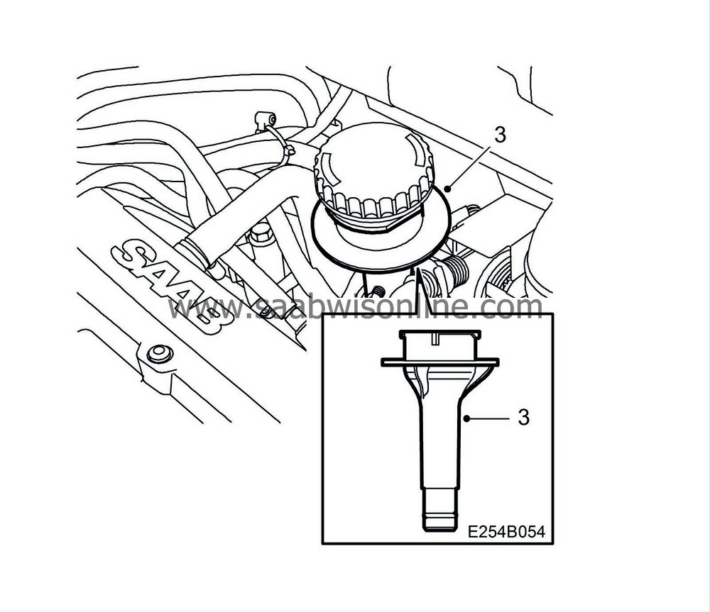
Fit a new oil filler pipe.
|
|
4.
|
Remove the hose from the pipe connection on the turbo's intake manifold.
|
|
5.
|
Remove the hoses from the nipple in the camshaft cover. Check the condition of the hoses, replace if necessary.
|
|
6.
|
Remove the old nipple and bushing from the camshaft cover and fit the new nipple and bushing.
|
|
8.
|

Remove the oil trap's two upper hoses.
|
|
9.
|
Remove the lower hose to the oil trap. Remove the stay to the intake manifold and the oil trap. If necessary, remove the generator positive cable.
|
|
10.
|
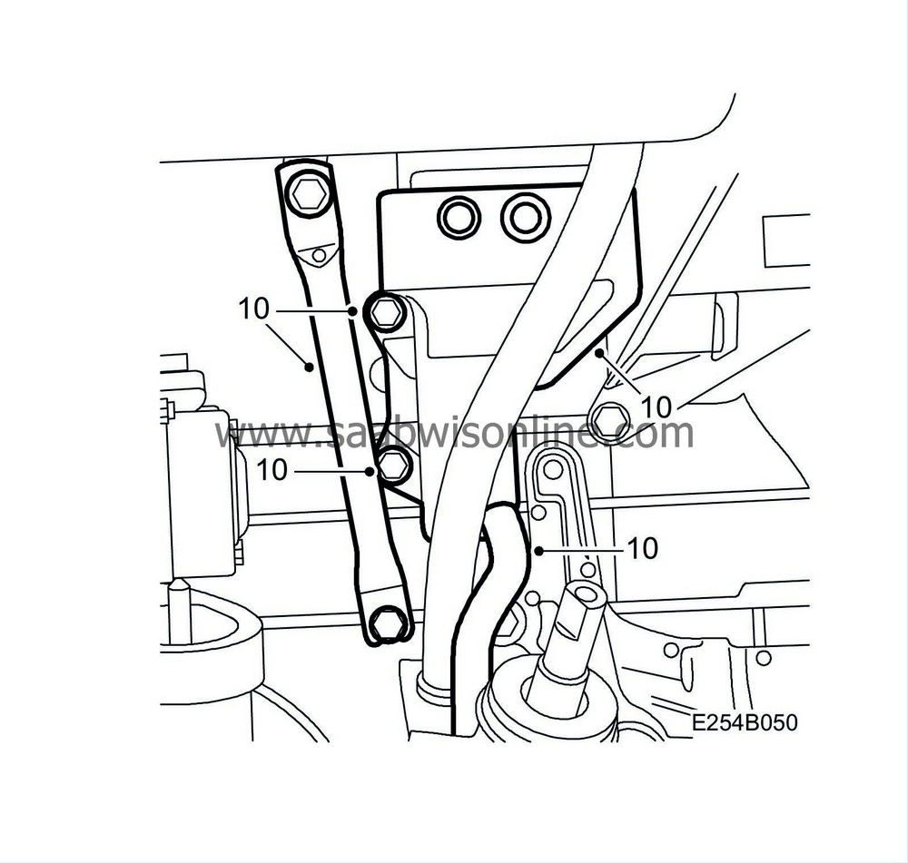
Fit the new oil trap, the lower hose to the oil trap (replace hose if necessary) and the stay for the intake manifold. If the positive cable was removed, connect it to the generator.
|
|
11.
|
Lower the car.
|
|
12.
|
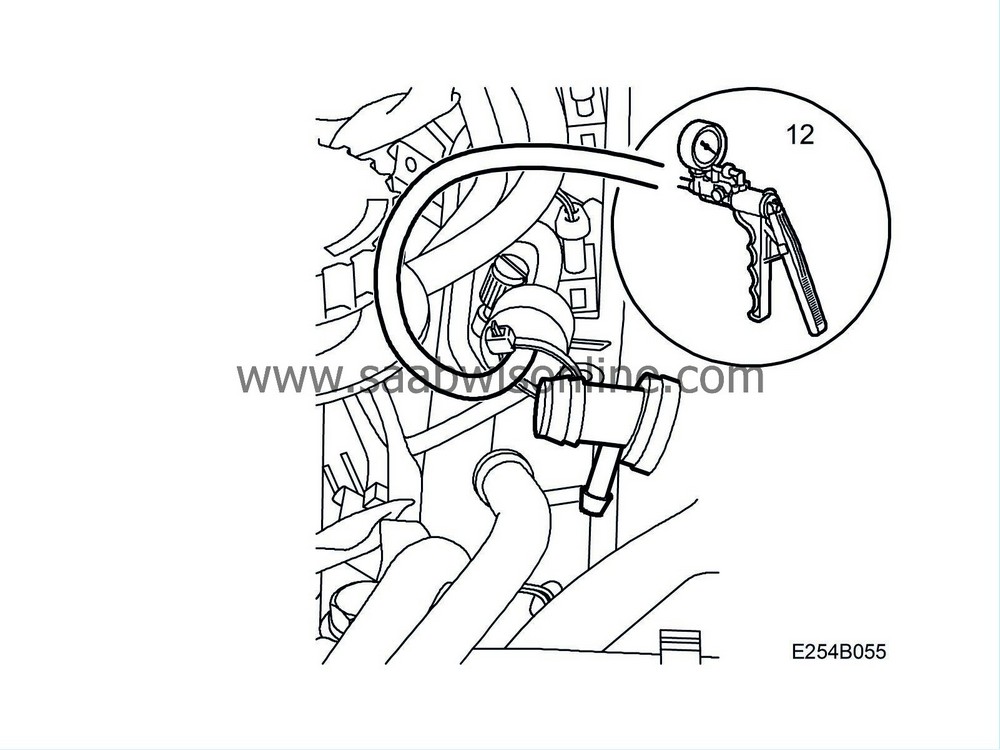
Check the function of the check valve on the small circuit with 30 14 883 Pressure/Vacuum pump, replace if necessary. The arrow must point toward the throttle body.
|
Note
|
|
Arrow's direction on the check valve.
|
|
|
13.
|

Connect the new hose kit (with T-connection) between the nipple on the oil filler pipe and the connection on the turbo's intake manifold.
|
|
14.
|
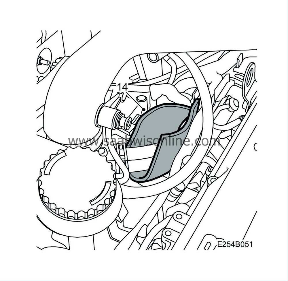
Fit the insulation under the throttle body's coolant hoses so that the insulation's short sides point upward.
|
|
15.
|
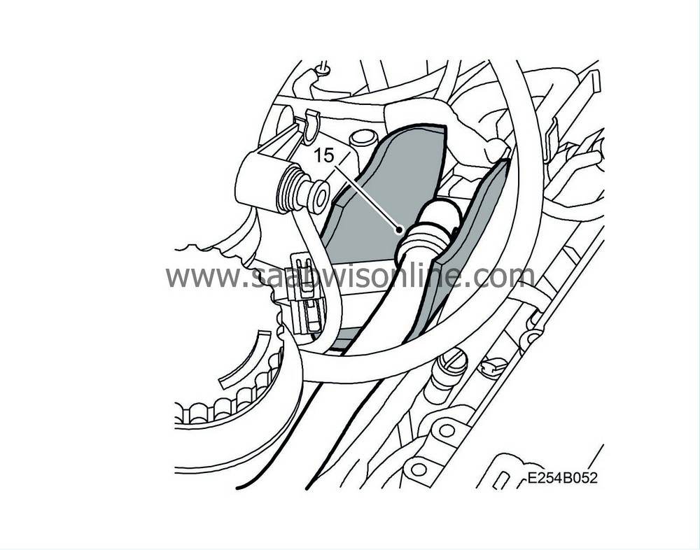
Fit the crankcase ventilation hose in place so that the check valve is located above the coolant hoses. The crankcase ventilation hose must follow the route of the lower coolant hose through the intake manifold and then on to the oil trap.
|
|
16.
|
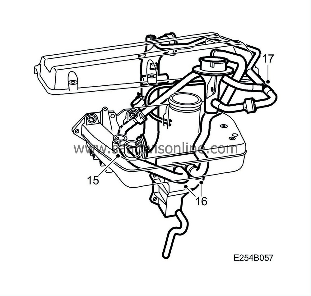
Connect the oil trap's upper hoses. If the hose with part no. 55 560 463 is replaced then the nipple enclosed with the hose must not be used. Use the nipple enclosed with the spare parts kit.
|
|
17.
|
Connect the new hose kit together at the T-connection.
|
|
18.
|
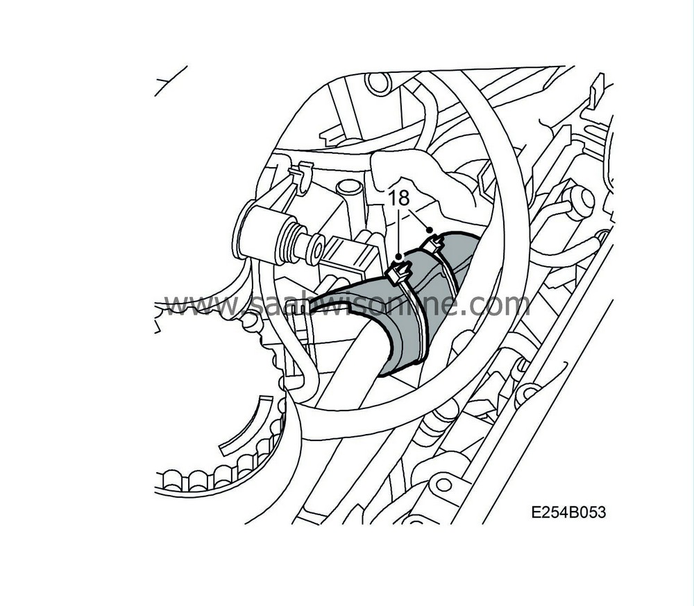
Make sure that the check valve has good contact with both coolant hoses. Affix a cable tie around the insulation on each side of the check valve.
|
|
19.
|
Fit the hoses to the nipple on the camshaft cover.
|
|
20.
|
Fit the upper engine cover.
|
|
21.
|
Connect the cable to the battery's negative terminal.
|
|
22.
|
Set the correct time and date in SID.
|
|
Fitting the mounting kit, crankcase ventilation, Saab 9-3 (9400)
|
|
1.
|
Disconnect the battery's negative cable.
|
|
2.
|
Remove the upper engine cover.
|
|
3.
|
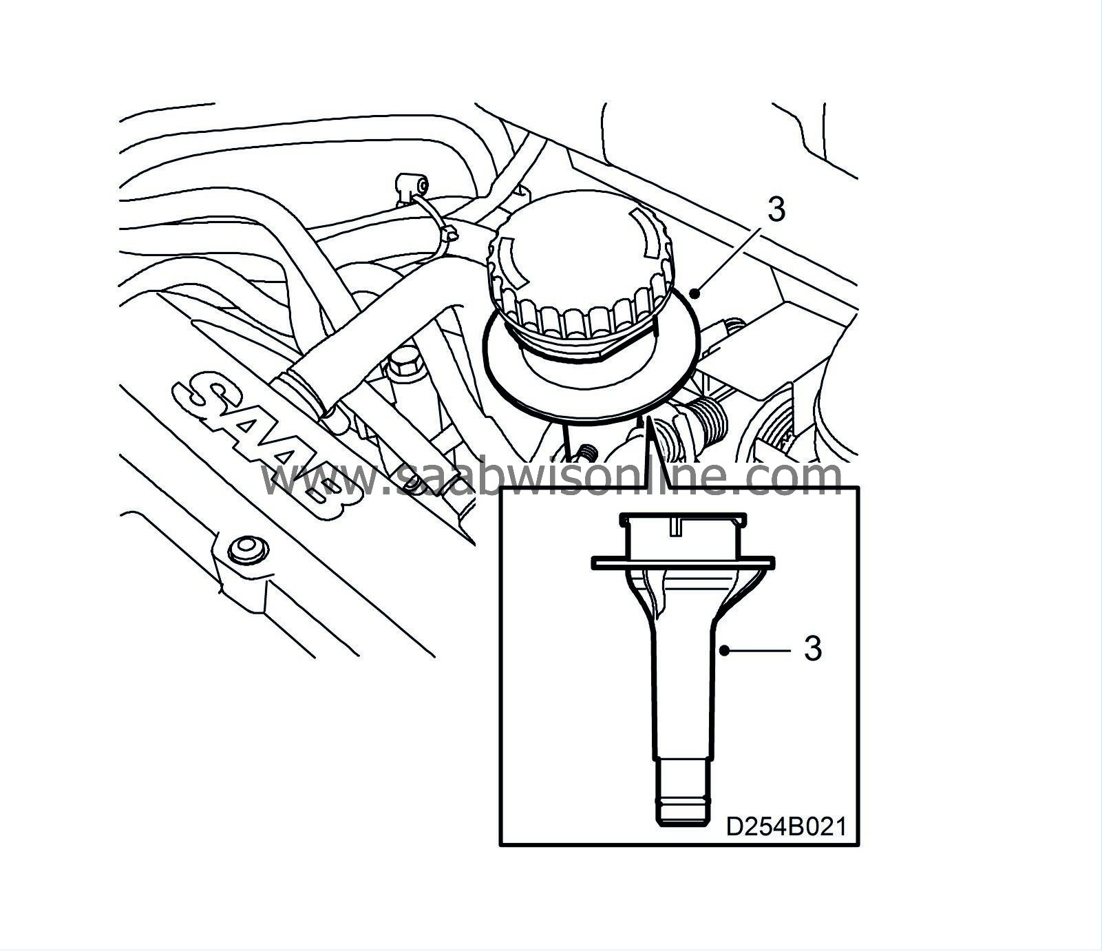
Fit a new oil filler pipe.
|
|
4.
|
Remove the hose from the pipe connection on the turbo's intake manifold.
|
|
5.
|
Remove the hoses from the nipple in the camshaft cover. Check the condition of the hoses, replace if necessary.
|
|
6.
|
Remove the old nipple and bushing from the camshaft cover and fit the new nipple and bushing.
|
|
8.
|
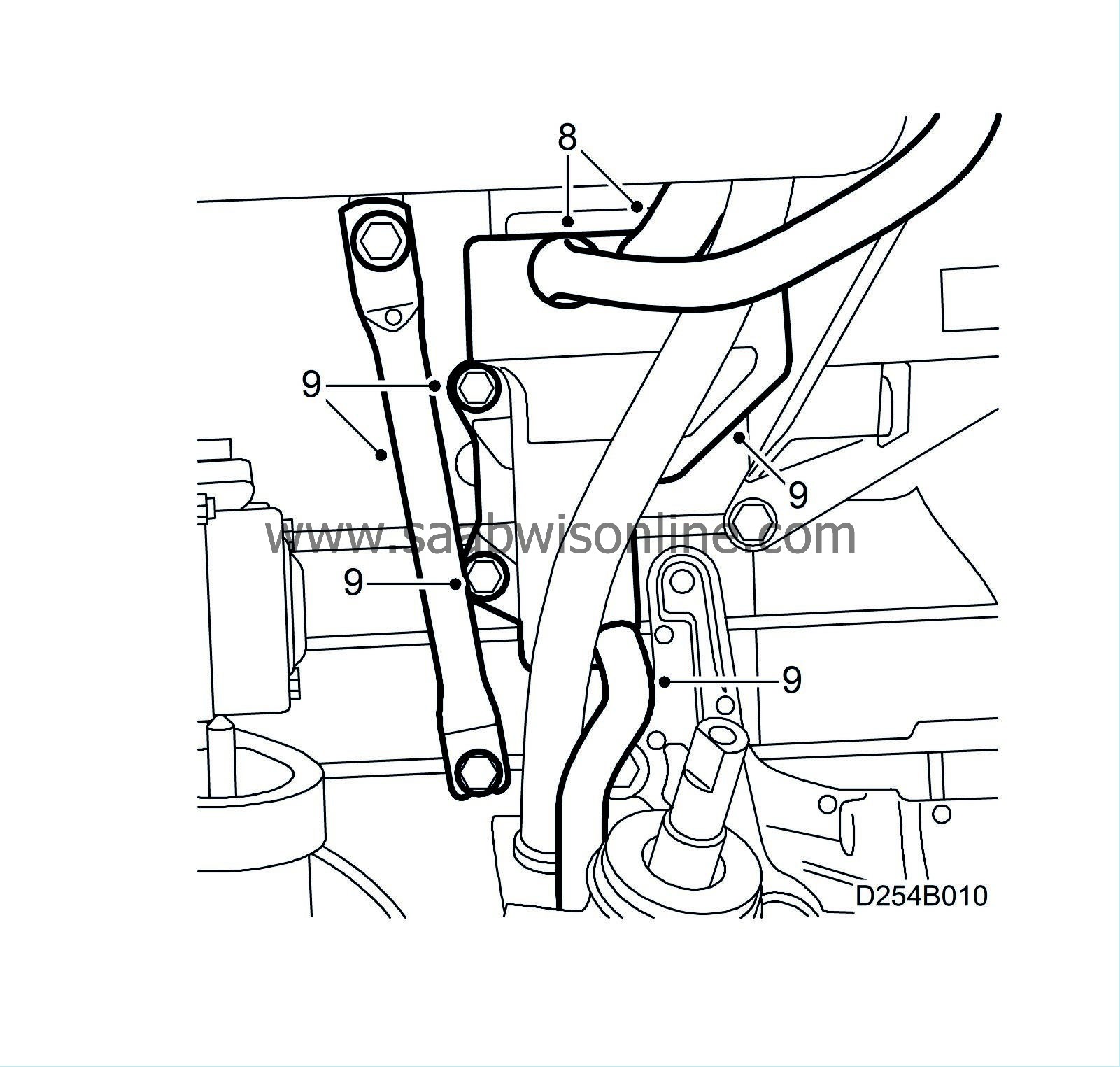
Remove the oil trap's two upper hoses.
|
|
9.
|
Remove the lower hose to the oil trap. Remove the stay to the intake manifold and the oil trap. If necessary, remove the generator positive cable.
|
|
10.
|
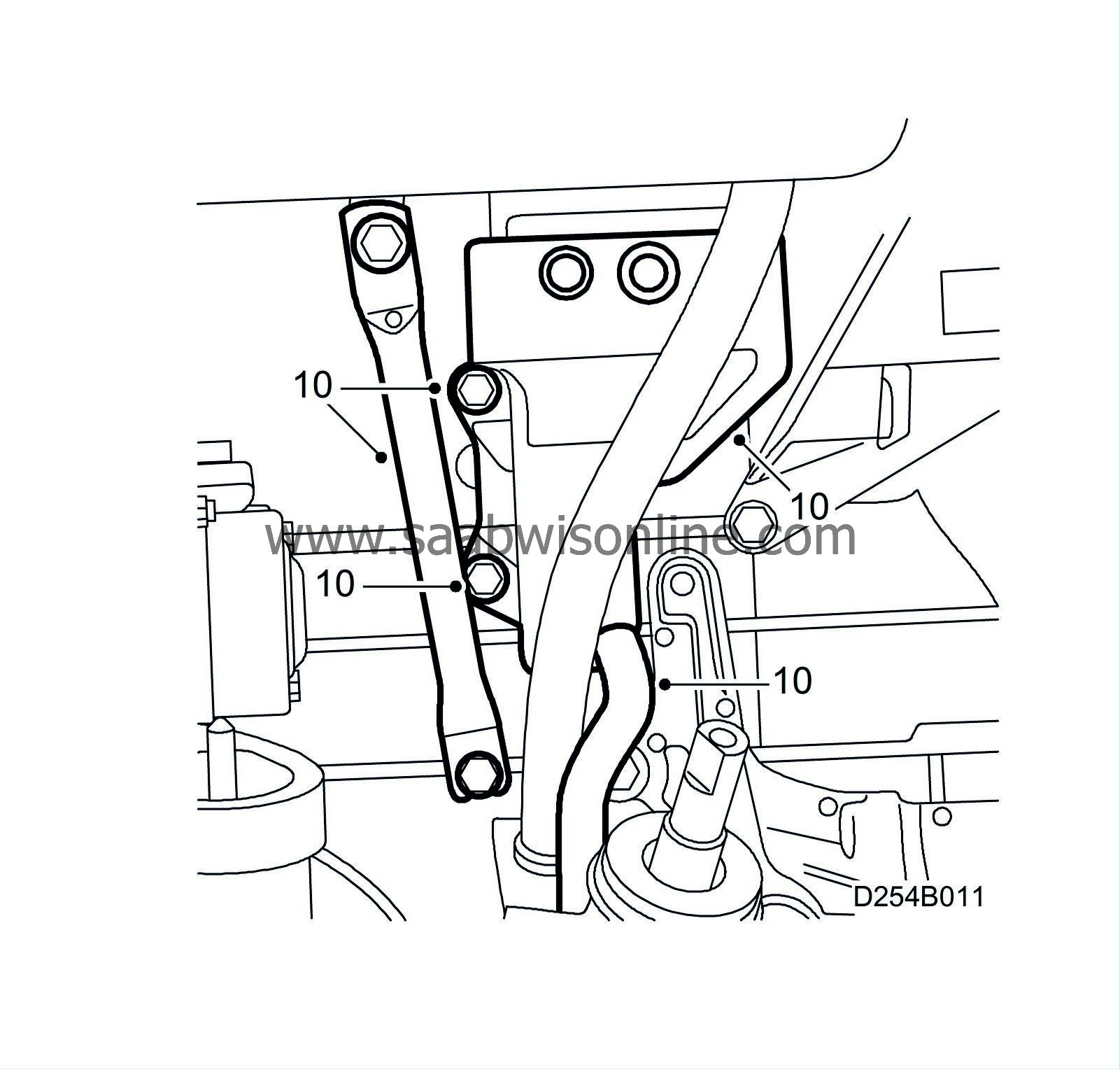
Fit the new oil trap, the lower hose to the oil trap (replace hose if necessary) and the stay for the intake manifold. If the positive cable was removed, connect it to the generator.
|
|
12.
|
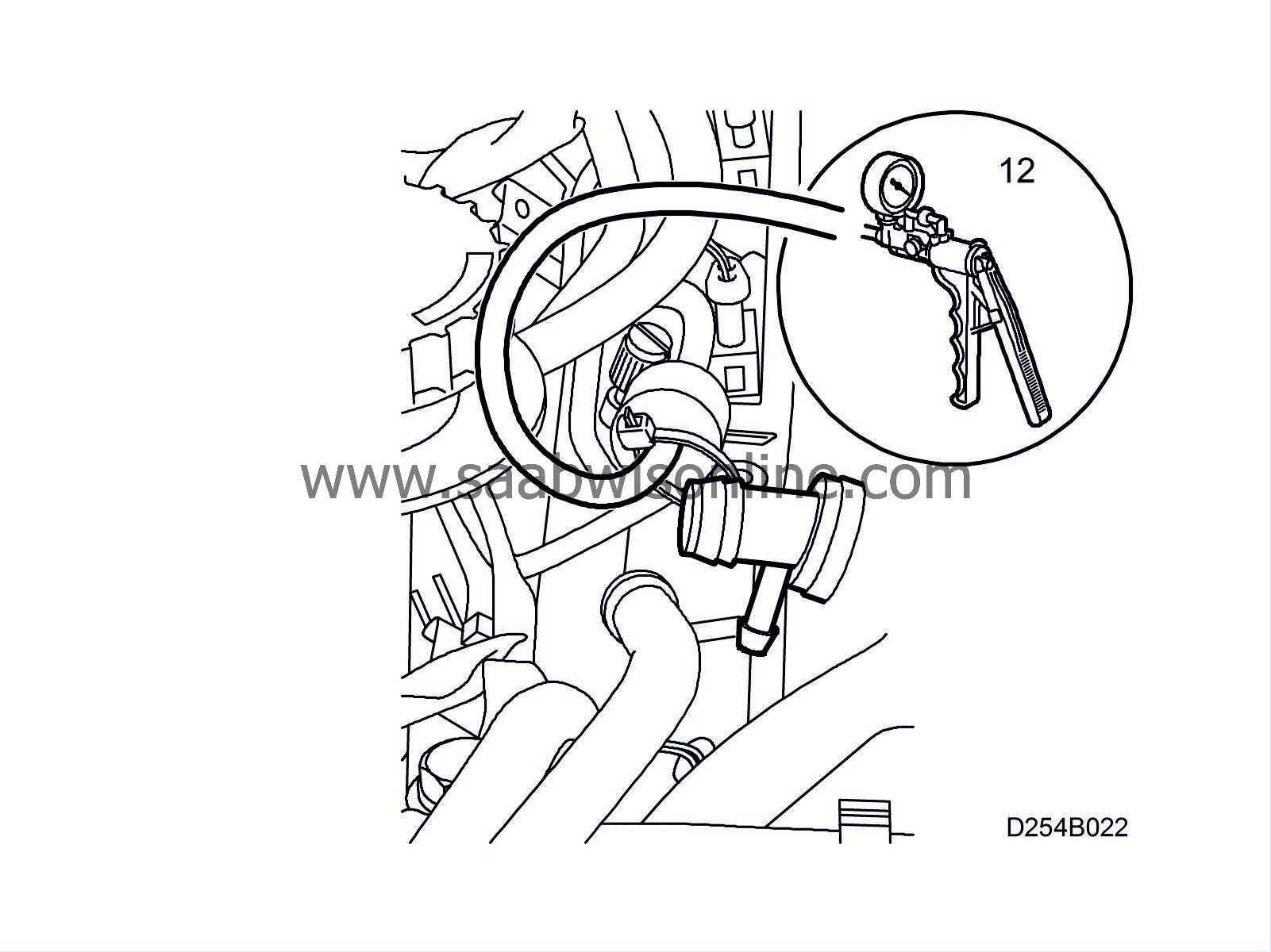
Check the function of the check valve on the small circuit with 30 14 883 Pressure/Vacuum pump, replace if necessary. The arrow must point toward the throttle body.
|
Note
|
|
Arrow's direction on the check valve.
|
|
|
13.
|
Man:
Remove the vacuum pipe from the turbocharger delivery pipe.
|
|
14.
|
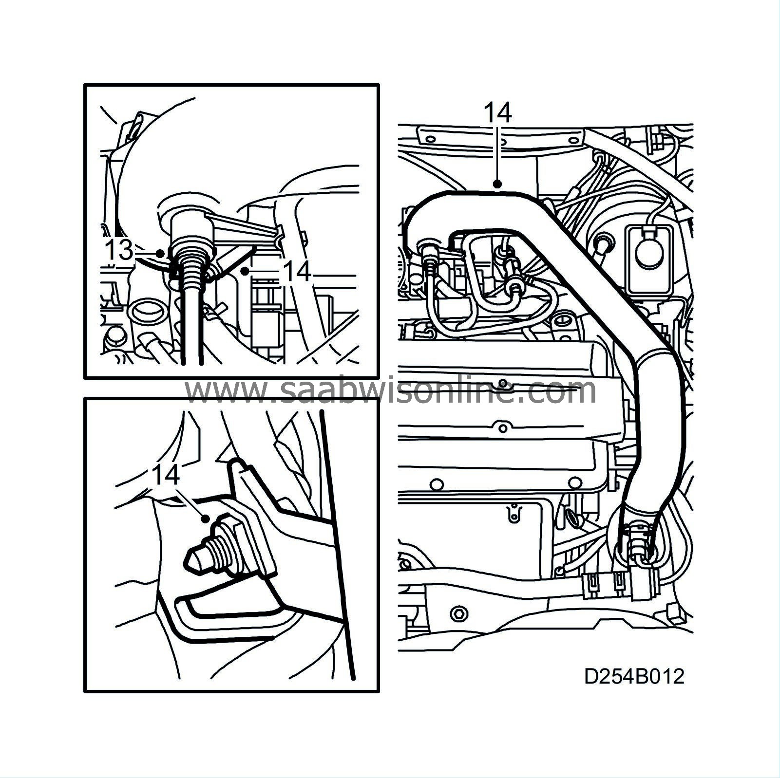
Remove the upper turbocharger delivery pipe from the throttle body and cylinder head. Move the turbocharger delivery pipe aside.
|
|
15.
|
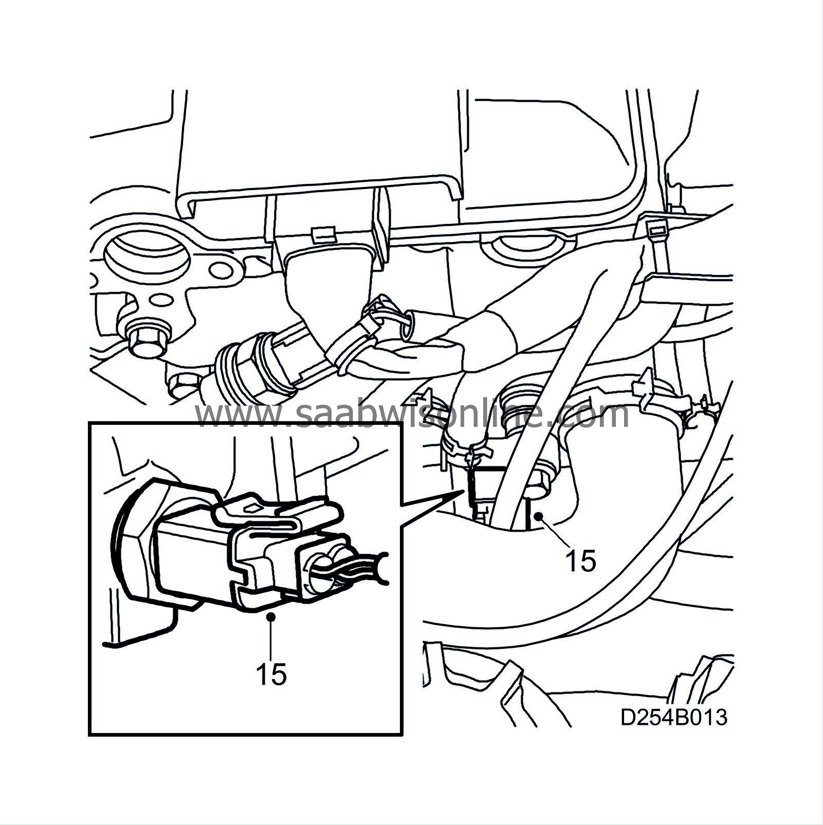
Unplug the temperature sensor connector.
|
|
16.
|
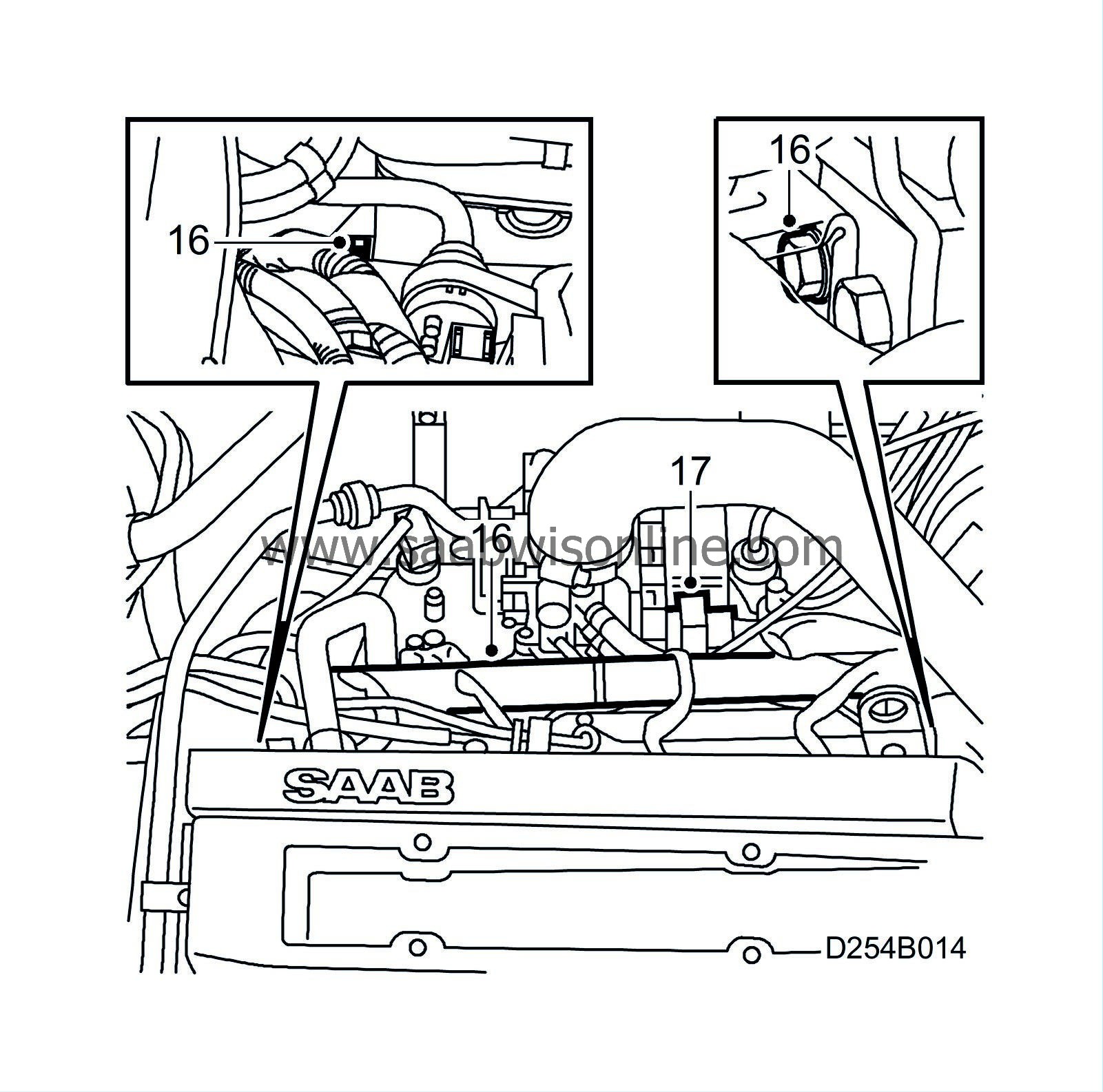
Detach and move aside the cable duct from the cylinder head.
|
|
17.
|
Unplug the throttle body connector.
|
|
18.
|
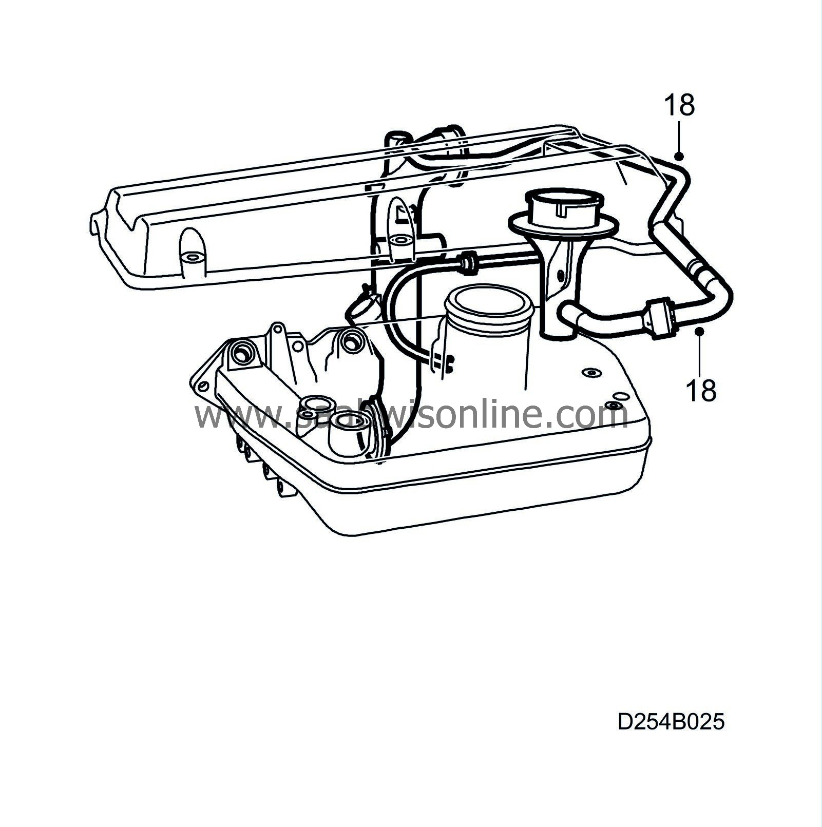
Connect the new hose kit (with T-connection) between the nipple on the oil filler pipe and the connection on the turbo's intake manifold.
|
|
19.
|
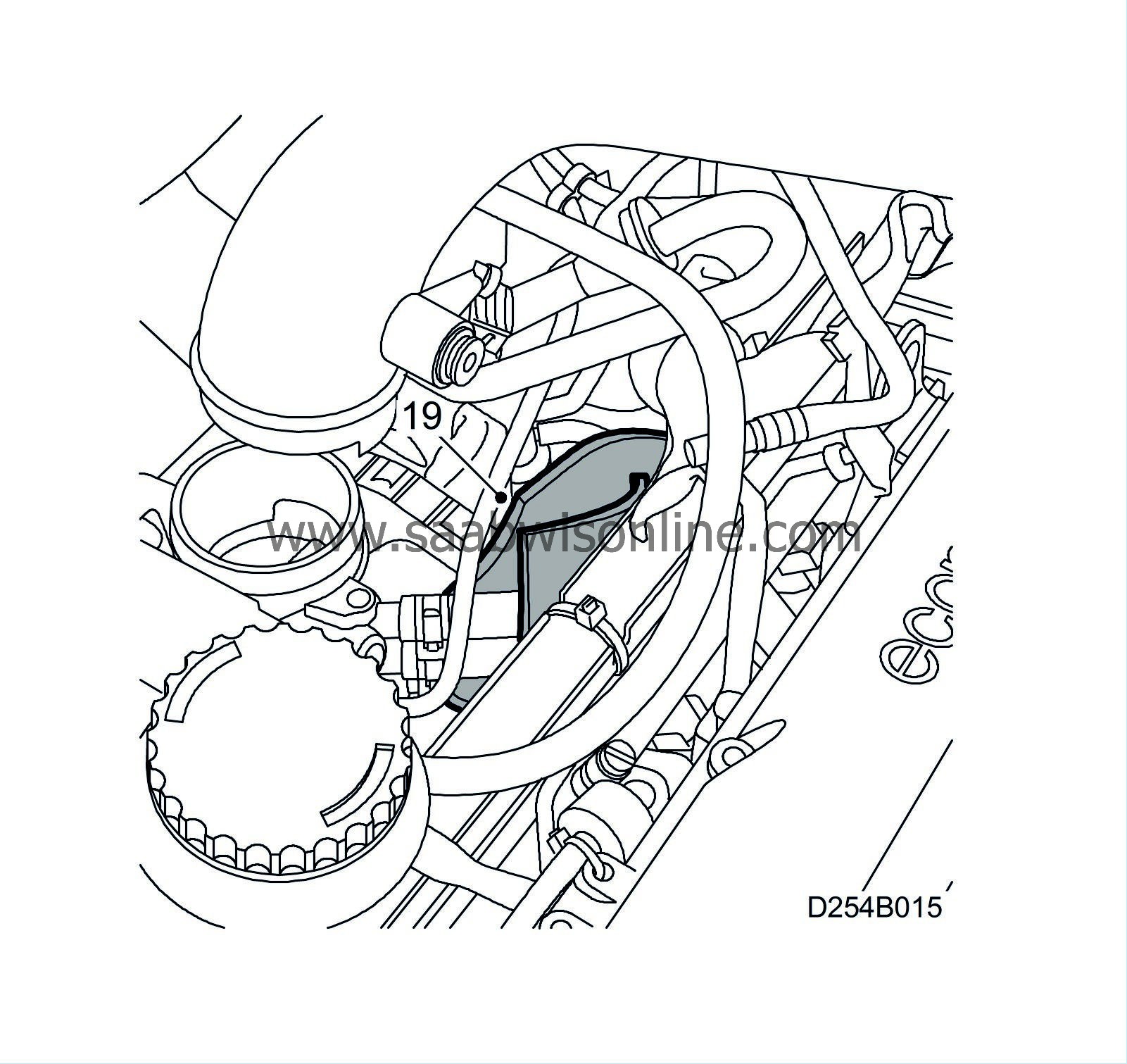
Fit the insulation under the throttle body's coolant hoses so that the insulation's short sides point upward.
|
|
20.
|
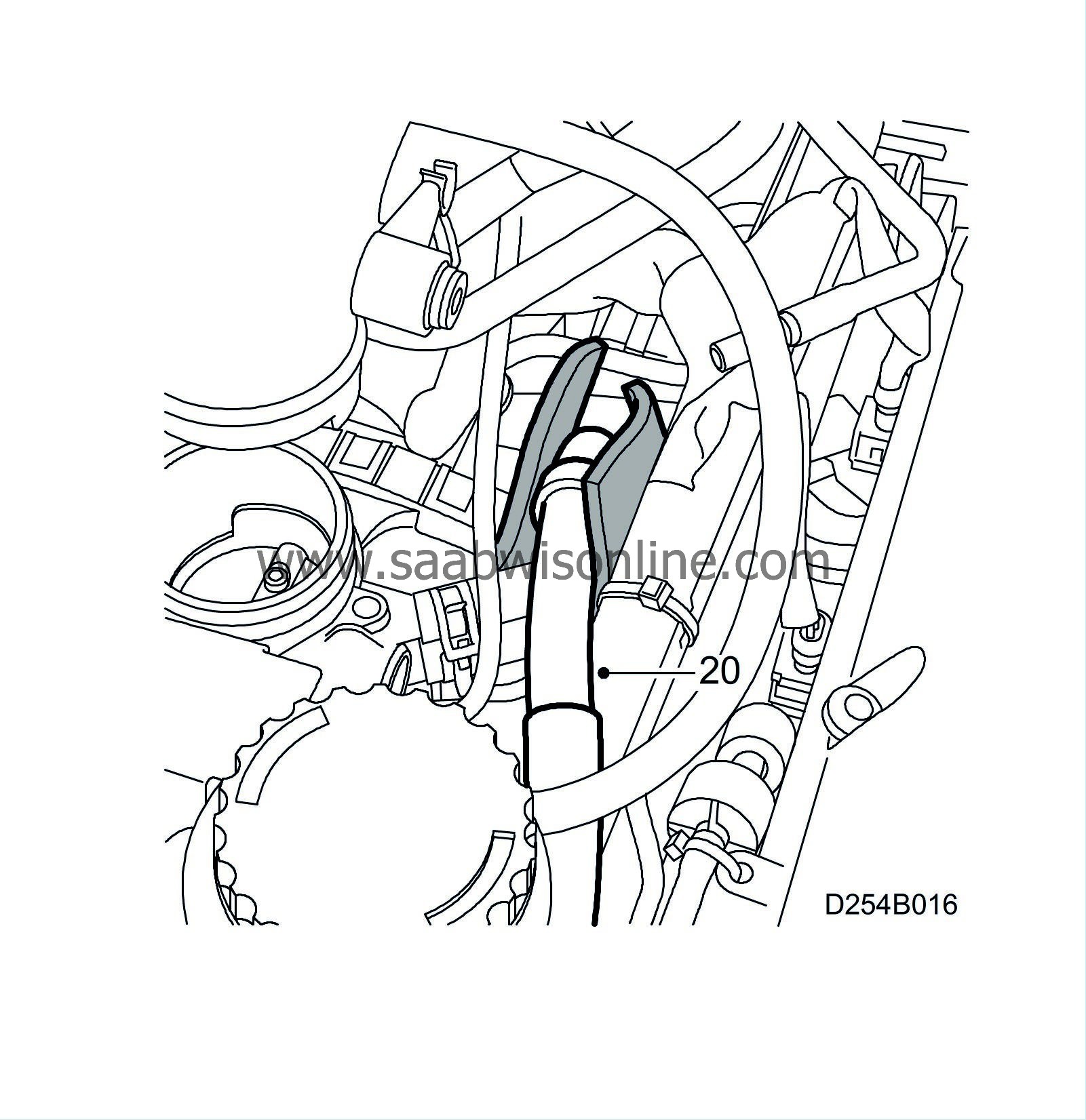
Fit the crankcase ventilation hose in place so that the check valve is located above the coolant hoses. The crankcase ventilation hose must follow the route of the lower coolant hose through the intake manifold and then on to the oil trap.
|
|
21.
|
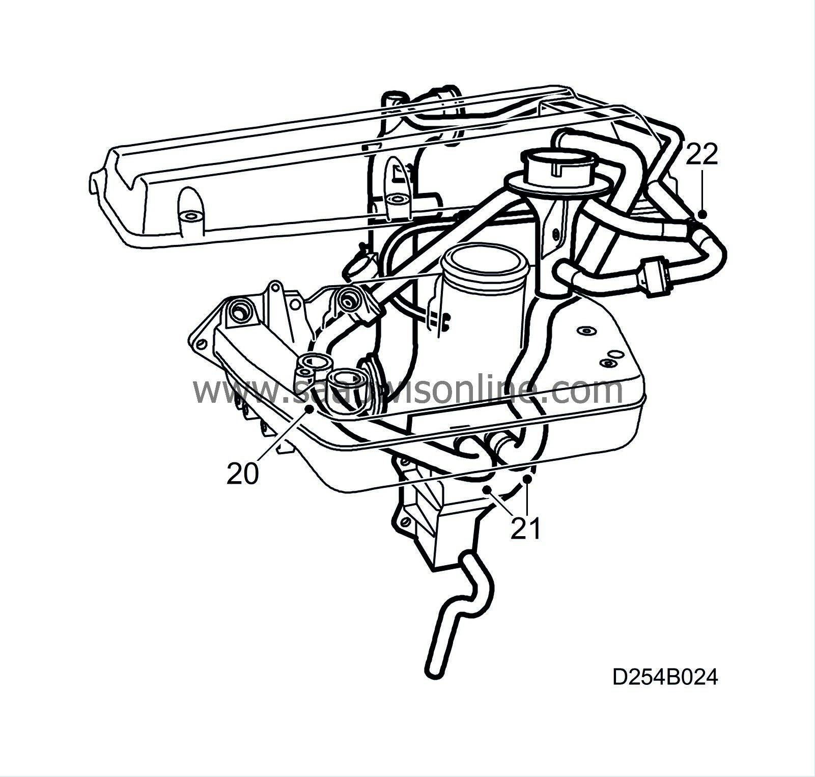
Connect the oil trap's upper hoses. If the hose with part no. 55 560 463 is replaced then the nipple enclosed with the hose must not be used. Use the nipple enclosed with the spare parts kit.
|
|
22.
|
Connect the new hose kit together at the T-connection.
|
|
23.
|
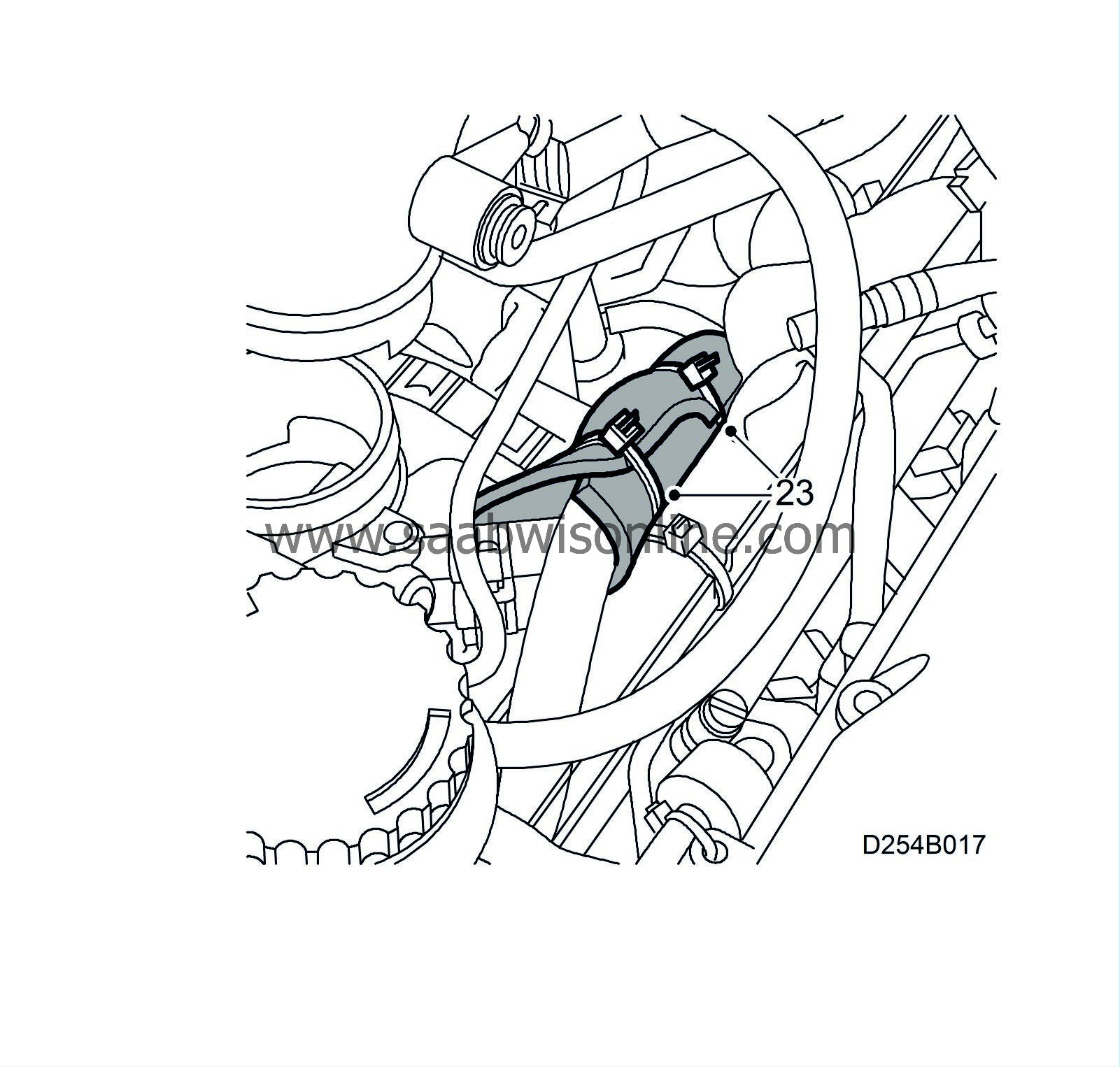
Make sure that the check valve has good contact with both coolant hoses. Affix a cable tie around the insulation on each side of the check valve.
|
|
24.
|
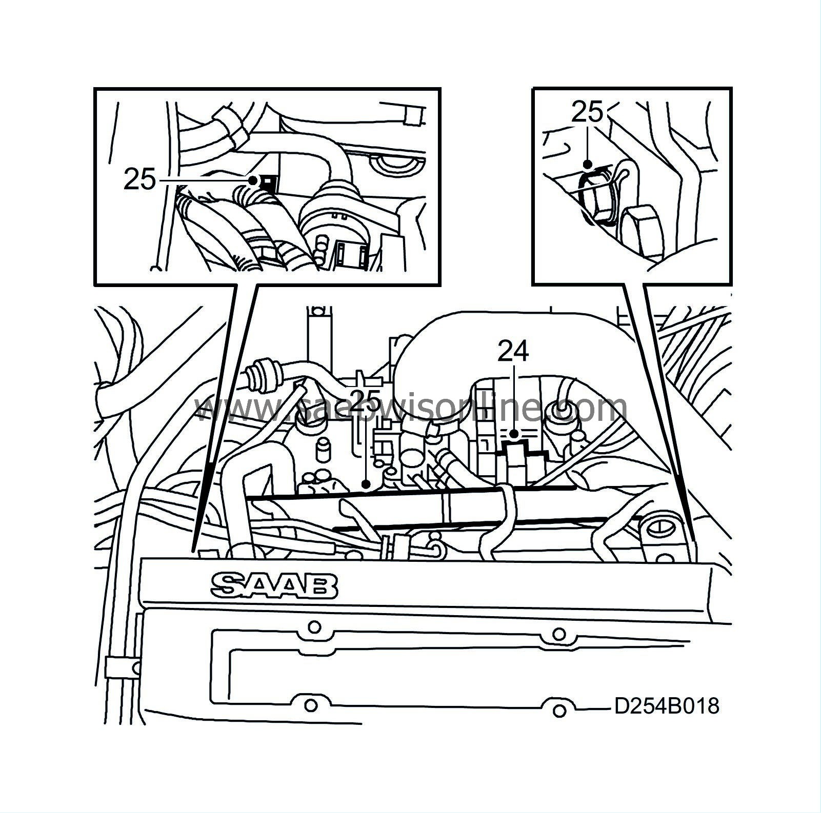
Plug the connector into the throttle body.
|
|
25.
|
Fit the cable duct to the cylinder head.
|
|
26.
|
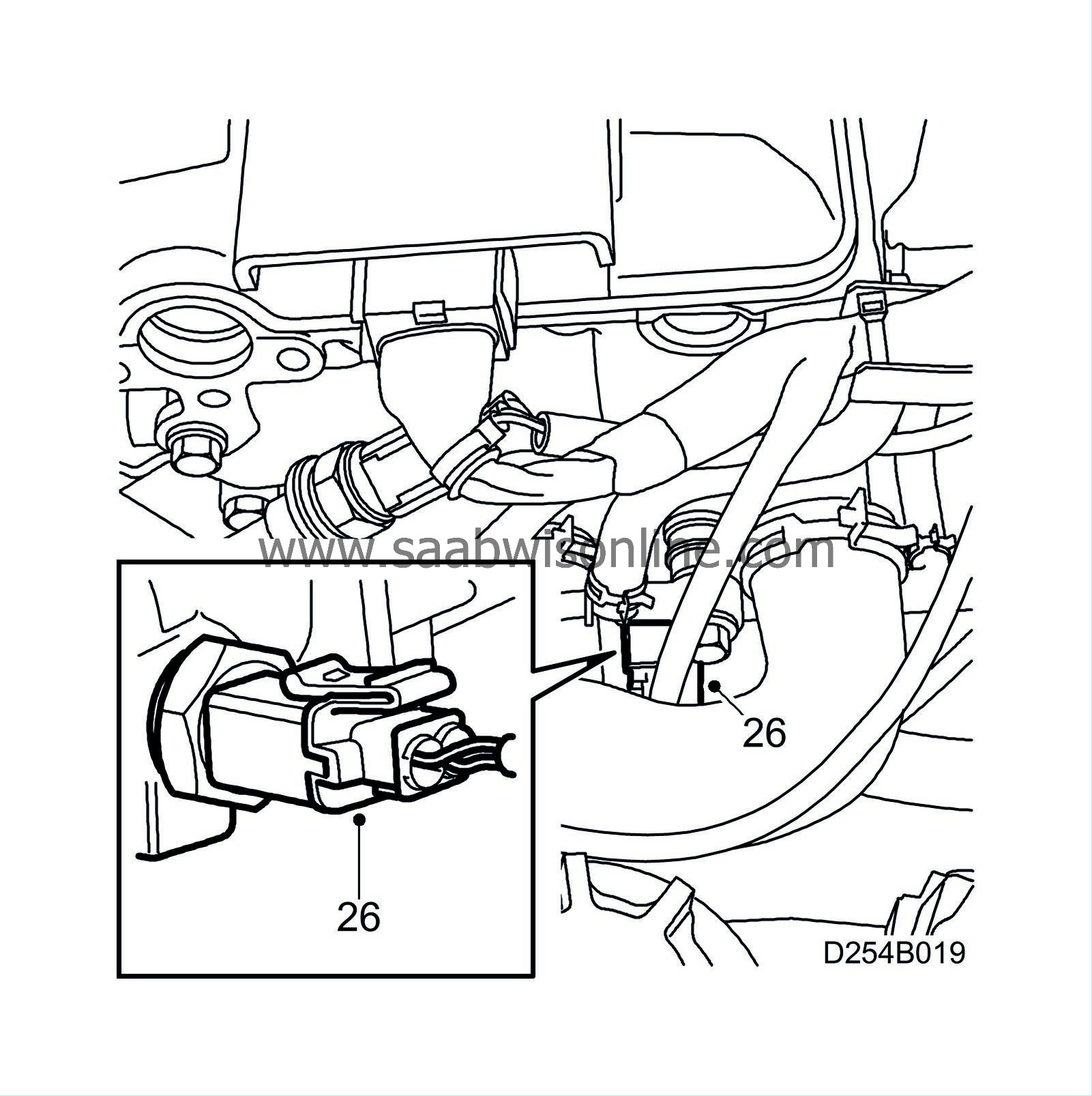
Plug the connector into the temperature sensor.
|
|
27.
|
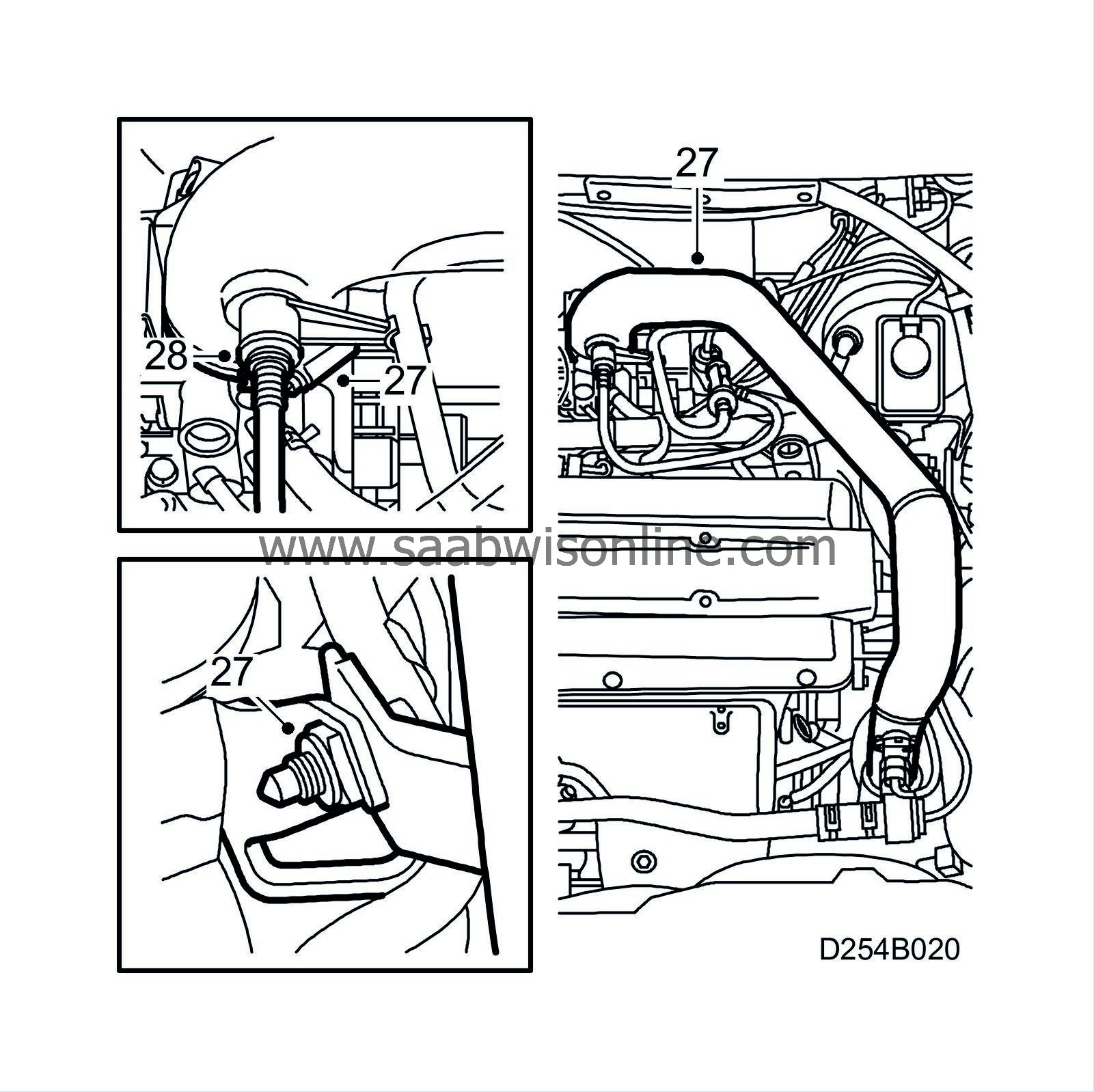
Fit the turbocharger delivery pipe. If necessary, replace the throttle body O-ring.
|
|
28.
|
Man:
Fit the vacuum pipe.
|
|
29.
|
Fit the hoses to the nipple on the camshaft cover.
|
|
30.
|
Fit the upper engine cover.
|
|
31.
|
Connect the cable to the battery's negative terminal.
|
|
32.
|
Set the correct time and date in SID.
|
|
Warranty/Time Information
|
Before the repair can be carried out approval must be obtained in accordance with normal process from the importer.
Check points 1 and 2:
Warranty claims cannot be made on these checks
Other points:
Fault/Reason code: 74
For Failed Object, Location codes and Repair/Action codes, see the Warranty/Time Information matrix appended to this TSB
|
Note
|
|
Labour Operations cannot be combined. They are designed so that they cover the repairs/action described above.
|


