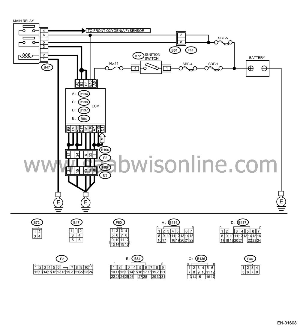
CHECK POWER SUPPLY AND GROUND LINE OF ENGINE CONTROL MODULE (ECM)
| CHECK POWER SUPPLY AND GROUND LINE OF ENGINE CONTROL MODULE (ECM) |
| Important | ||
|
After repair
or replacement of faulty parts, conduct Clear Memory Mode
|
||
WIRING DIAGRAM:

CHECK MAIN RELAY.
Turn the ignition switch to OFF.Remove the main relay.
Connect the battery to main relay terminals No. 1 and No. 2.
Measure the resistance between main relay terminals.
Terminals
No. 3 — No. 5:
No. 4 — No. 6:
Is the resistance less than 10 Ω?
| Yes |
| No |
Replace the main relay.
CHECK GROUND CIRCUIT OF ECM.
Disconnect the connector from ECM.Measure the resistance of harness between ECM and chassis ground.
Connector & terminal
(B134) No. 7 — Chassis ground:
(B134) No. 15 — Chassis ground:
(B134) No. 22 — Chassis ground:
(B136) No. 1 — Chassis ground:
(B137) No. 8 — Chassis ground:
(B137) No. 17 — Chassis ground:
(B137) No. 18 — Chassis ground:
(B84) No. 8 — Chassis ground:
(B84) No. 9 — Chassis ground:
Is the resistance less than 5 Ω?
| Yes |
| No |
Repair the open circuit in harness between ECM connector and engine grounding terminal.
CHECK INPUT VOLTAGE OF ECM.
Measure the voltage between ECM connector and chassis ground.Connector & terminal
(B84) No. 10 (+) — Chassis ground (−): (B134) No. 5 (+) — Chassis ground (−):
Is the voltage more than 10 V?
| Yes |
| No |
Repair the open or ground short circuit of power supply circuit.
CHECK HARNESS BETWEEN ECM AND MAIN RELAY CONNECTOR.
Turn the ignition switch to OFF.Measure the resistance between ECM and chassis ground.
Connector & terminal
(B134) No. 6 — Chassis ground:
Is the resistance more than 1 MΩ?
| Yes |
| No |
Repair the ground short circuit in harness between ECM connector and main relay connector, and then replace ECM.
CHECK OUTPUT VOLTAGE FROM ECM.
Connect the connector to ECM.Turn the ignition switch to ON.
Measure the voltage between ECM connector and chassis ground.
Connector & terminal
(B134) No. 6 (+) — Chassis ground (−):
Is the voltage more than 10 V?
| Yes |
| No |
CHECK INPUT VOLTAGE OF MAIN RELAY.
Check the voltage between main relay connector and chassis ground.Connector & terminal
(B47) No. 2 (+) — Chassis ground (−):
Is the voltage more than 10 V?
| Yes |
| No |
Repair the open circuit in harness between ECM connector and main relay connector.
CHECK GROUND CIRCUIT OF MAIN RELAY.
Turn the ignition switch to OFF.Measure the resistance between main relay connector and chassis ground.
Connector & terminal
(B47) No. 1 — Chassis ground:
Is the resistance less than 5 Ω?
| Yes |
| No |
Repair the open circuit between main relay and chassis ground.
CHECK INPUT VOLTAGE OF MAIN RELAY.
Measure the voltage between main relay connector and chassis ground.Connector & terminal
(B47) No. 5 (+) — Chassis ground (−):
(B47) No. 6 (+) — Chassis ground (−):
Is the voltage more than 10 V?
| Yes |
| No |
Repair the open or ground short circuit in harness of power supply circuit.
CHECK INPUT VOLTAGE OF ECM.
Connect the main relay connector.Turn the ignition switch to ON.
Measure the voltage between ECM connector and chassis ground.
Connector & terminal
(B84) No. 2 (+) — Chassis ground (−):
(B84) No. 3 (+) — Chassis ground (−):
Is the voltage more than 10 V?
| Yes |
Check the ignition control system.

| No |
Repair the open or ground short circuit in harness between ECM connector and main relay connector.


