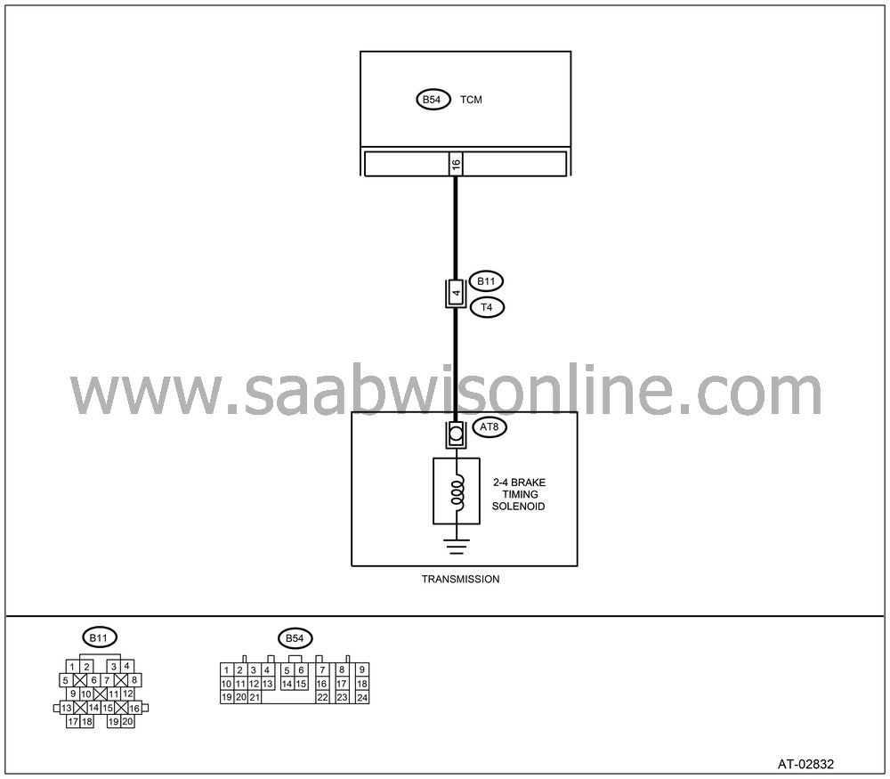
DTC 74 2-4 BRAKE TIMING SOLENOID
| DTC 74 2-4 BRAKE TIMING SOLENOID |
DIAGNOSIS:
The output signal circuit of 2-4 brake timing solenoid is open or shorted.
TROUBLE SYMPTOM:
Excessive shift shock.
WIRING DIAGRAM:

CHECK HARNESS CONNECTOR BETWEEN TCM AND TRANSMISSION.
Turn the ignition switch to OFF.Disconnect the connector from TCM and transmission.
Measure the resistance of harness between TCM and transmission connector.
Connector & terminal
(B54) No. 16 — (B11) No. 4:
Is the resistance less than 1 Ω?
| Yes |
| No |
Repair the open circuit in harness between TCM and transmission connector.
CHECK HARNESS CONNECTOR BETWEEN TCM AND TRANSMISSION.
Measure the resistance of harness between TCM connector and chassis ground.Connector & terminal
(B54) No. 16 — Chassis ground:
Is the resistance more than 1 MΩ?
| Yes |
| No |
Repair the short circuit in harness between TCM and transmission connector.
CHECK 2-4 BRAKE TIMING SOLENOID.
Measure the resistance between transmission connector terminals.Connector & terminal
(T4) No. 4 — No. 16:
Is the resistance 10 — 16 Ω?
| Yes |
| No |
CHECK OUTPUT SIGNAL EMITTED FROM TCM.
Connect the connectors to TCM and transmission.Turn the ignition switch to ON (engine OFF).
Move the select lever to “D” range.
Measure the voltage between TCM connector and chassis ground.
Connector & terminal
(B54) No. 15 (+) — Chassis ground (−):
Is the voltage more than 9 V?
| Yes |
| No |
CHECK OUTPUT SIGNAL EMITTED FROM TCM.
Connect the connectors to TCM and transmission.Lift-up the vehicle and support with rigid rack.
| Note | ||
|
Raise all wheels off ground. |
Start the engine and warm-up the transmission until ATF temperature is above 80°C (176°F).
| Note | ||
|
If ambient temperature is below 0°C (32°F), drive the vehicle until ATF reaches its operating temperature. |
Move the selector lever to “1” range, and slowly increase vehicle speed to 10 km/h (6 MPH).
Measure the voltage between TCM connector and chassis ground.
Connector & terminal
(B54) No. 16 (+) — Chassis ground (−):
Is the voltage less than 1 V?
| Yes |
Even if the AT OIL TEMP warning light blinks, the circuit has returned to a normal condition at this time. A temporary poor contact of the connector or harness may be the cause. Repair the harness or connector in low clutch timing solenoid and transmission.
| No |
CHECK POOR CONTACT.
Is there poor contact in 2-4 brake timing solenoid circuit?
| Yes |
Repair the poor contact.
| No |
CHECK 2-4 BRAKE TIMING SOLENOID (IN TRANSMISSION).
Remove the transmission connector from bracket.Lift-up the vehicle and support with rigid rack.
| Note | ||
|
Raise all wheels off ground. |
Drain the ATF.
| Important | ||
|
Do not drain the ATF until it cools down. |
||
Remove the oil pan, and disconnect connector from 2-4 brake timing solenoid.
Measure the resistance between 2-4 brake timing solenoid connector and transmission ground.
Terminals
No. 1 — Transmission ground:
Is the resistance 10 — 16 Ω?
| Yes |
| No |
Replace the 2-4 brake timing solenoid.

CHECK HARNESS CONNECTOR BETWEEN 2-4 BRAKE TIMING SOLENOID AND TRANSMISSION.
Measure the resistance of harness between 2-4 brake timing solenoid and transmission connector.Connector & terminal
(AT8) No. 1 — (T4) No. 4:
Is the resistance less than 1 Ω?
| Yes |
| No |
Repair the open circuit in harness between 2-4 brake timing solenoid and transmission connector.
CHECK HARNESS CONNECTOR BETWEEN 2-4 BRAKE TIMING SOLENOID AND TRANSMISSION.
Measure the resistance of harness between 2-4 brake timing solenoid connector and transmission ground.Connector & terminal
(T4) No. 4 — Transmission ground:
Is the resistance more than 1 MΩ?
| Yes |
Even if the AT OIL TEMP warning light blinks, the circuit has returned to a normal condition at this time. A temporary poor contact of the connector or harness may be the cause. Repair the harness or connector in 2-4 brake timing solenoid and transmission.
| No |
Repair the short circuit harness between 2-4 brake timing solenoid and transmission connector.


