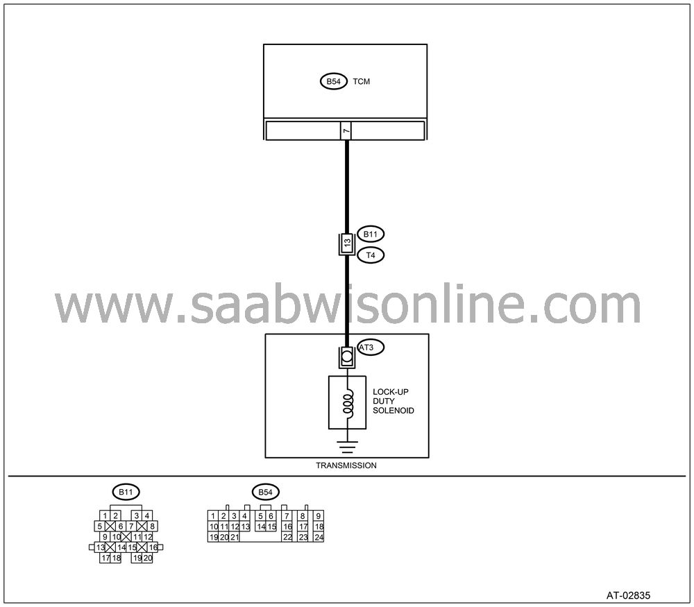
DTC 77 LOCK-UP DUTY SOLENOID
| DTC 77 LOCK-UP DUTY SOLENOID |
DIAGNOSIS:
The output signal circuit of lock-up duty solenoid is open or shorted.
TROUBLE SYMPTOM:
No “lock-up” (after engine warm-up).
WIRING DIAGRAM:

CHECK HARNESS CONNECTOR BETWEEN TCM AND TRANSMISSION.
Turn the ignition switch to OFF.Disconnect the connector from TCM and transmission.
Measure the resistance of harness between TCM and transmission connector.
Connector & terminal
(B54) No. 7 — (B11) No. 13:
Is the resistance less than 1 Ω?
| Yes |
| No |
Repair the open circuit in harness between TCM and transmission connector.
CHECK HARNESS CONNECTOR BETWEEN TCM AND TRANSMISSION.
Measure the resistance of harness connector between TCM and chassis ground.Connector & terminal
(B54) No. 7 — Chassis ground:
Is the resistance more than 1 MΩ?
| Yes |
| No |
Repair the short circuit in harness between TCM and transmission connector.
CHECK LOCK-UP DUTY SOLENOID.
Measure the resistance between transmission connector receptacle’s terminals.Connector & terminal
(T4) No. 13 — No. 16:
Is the resistance 10 — 17 Ω?
| Yes |
| No |
CHECK OUTPUT SIGNAL EMITTED FROM TCM USING Vehicle Diagnostic Interface.
Connect the connectors to TCM and transmission.Lift-up the vehicle and support with rigid racks.
| Note | ||
|
Raise all wheels off ground. |
Connect the Vehicle Diagnostic Interface to data link connector.
Start the engine and turn Vehicle Diagnostic Interface switch to ON.
Start the engine and warm-up the transmission until ATF temperature is above 80°C (176°F).
| Note | ||
|
If ambient temperature is below 0°C (32°F), drive the vehicle until ATF reaches its operating temperature. |
Read the data of lock-up duty solenoid using Vehicle Diagnostic Interface.
| • |
Lock-up
duty solenoid is indicated in “%”.
|
|
Move the selector lever to “D” range and slowly increase vehicle speed to 75 km/h (47 MPH). Wheels will lock-up.
Is the value 95%?
| Yes |
| No |
CHECK OUTPUT SIGNAL EMITTED FROM TCM USING Vehicle Diagnostic Interface.
Return the engine to idling speed and move selector lever to “N” range.Is the value 5%?
| Yes |
Even if the AT OIL TEMP warning light blinks, the circuit has returned to a normal condition at this time. A temporary poor contact of the connector or harness may be the cause. Repair the harness or connector in TCM and transmission.
| No |
CHECK POOR CONTACT.
Is there poor contact in lock-up duty solenoid circuit?
| Yes |
Repair poor contact.
| No |
CHECK LOCK-UP DUTY SOLENOID (IN TRANSMISSION).
Remove the transmission connector from bracket.Drain the ATF.
| Important | ||
|
Do not drain the ATF until it cools down. |
||
Remove the oil pan and disconnect connector from lock-up duty solenoid.
Measure the resistance between lock-up duty solenoid connector and transmission ground.
Terminals
No. 1 — Transmission ground:
Is the resistance 10 — 17 Ω?
| Yes |
| No |
Replace the lock-up duty solenoid.

CHECK HARNESS CONNECTOR BETWEEN LOCK-UP DUTY SOLENOID AND TRANSMISSION.
Measure the resistance of harness between lock-up duty solenoid and transmission connector.Connector & terminal
(T4) No. 13 — (AT3) No. 1:
Is the resistance less than 1 Ω?
| Yes |
| No |
Repair the open circuit in harness between TCM and transmission connector.
CHECK HARNESS CONNECTOR BETWEEN LOCK-UP DUTY SOLENOID AND TRANSMISSION.
Measure the resistance of harness between transmission connector and transmission ground.Connector & terminal
(T4) No. 13 — Transmission ground:
Is the resistance more than 1 MΩ?
| Yes |
Even if the AT OIL TEMP warning light blinks, the circuit has returned to a normal condition at this time. A temporary poor contact of the connector or harness may be the cause. Repair the harness or connector in lock-up duty solenoid and transmission.
| No |
Repair the short circuit in harness between lock-up duty solenoid and transmission connector.


