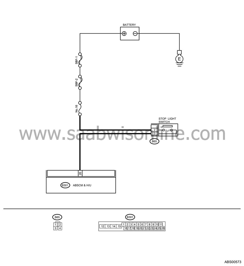
DTC 54 STOP LIGHT SWITCH SIGNAL CIRCUIT MALFUNCTION
| DTC 54 STOP LIGHT SWITCH SIGNAL CIRCUIT MALFUNCTION |
CHECK OUTPUT OF STOP LIGHT SWITCH USING Vehicle Diagnostic Interface.
Select “Current data display & Save” on the Vehicle Diagnostic Interface.Release the brake pedal.
Read the stop light switch output in Vehicle Diagnostic Interface data display.
Is “OFF” displayed on the display?
| Yes |
| No |
CHECK OUTPUT OF STOP LIGHT SWITCH USING Vehicle Diagnostic Interface.
Depress the brake pedal.Read the stop light switch output in Vehicle Diagnostic Interface data display.
Is “ON” displayed on the display?
| Yes |
| No |
CHECK IF STOP LIGHTS COME ON.
Depress the brake pedal.Do the stop lights turn on?
| Yes |
| No |
Repair the stop lights circuit.
CHECK OPEN CIRCUIT IN HARNESS.
Turn the ignition switch to OFF.Disconnect the connector from ABSCM& H/U.
Depress the brake pedal.
Measure the voltage between ABSCM&H/U connector and chassis ground.
Connector & terminal
(B301) No. 20 (+) — Chassis ground (−):
Is the voltage 10 — 15 V?
| Yes |
| No |
Repair the harness between stop light switch and ABSCM&H/U connector.
CHECK POOR CONTACT IN CONNECTORS.
Is there poor contact in connector between stop light switch and ABSCM&H/U?
| Yes |
| No |
Repair the connector.
CHECK ABSCM&H/U.
Connect all connectors.Erase the memory.
Perform the inspection mode.
Read out the DTC.
Is the same DTC as in current diagnosis still being output?
| Yes |
| No |
CHECK ANY OTHER DTC APPEARANCE.
Are other DTCs being output?
| Yes |
Proceed with the diagnosis corresponding to DTC.
| No |
A temporary poor contact.


