INSPECTION
| INSPECTION |
| COMMUNICATION FOR INITIALIZING IMPOSSIBLE |
DETECTING CONDITION:
Faulty harness connector
TROUBLE SYMPTOM:
Communication cannot be executed between ABS and Vehicle Diagnostic Interface.
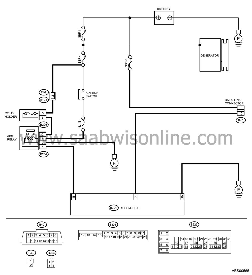
WIRING DIAGRAM:

CHECK IGNITION SWITCH.
Is the ignition switch turned to ON?
| Yes |
| No |
Turn the ignition switch to ON, and select ABS mode using Vehicle Diagnostic Interface.
CHECK BATTERY.
Turn the ignition switch to OFF.Measure the battery voltage.
Is the voltage more than 11 V?
| Yes |
| No |
Charge or replace the battery.
CHECK BATTERY TERMINAL.
Is there poor contact at battery terminal?
| Yes |
Repair or tighten the battery terminal.
| No |
CHECK COMMUNICATION OF Vehicle Diagnostic Interface.
Turn the ignition switch to ON.Using the Vehicle Diagnostic Interface, check whether communication to other system can be executed normally.
Are the name and year of system displayed on Vehicle Diagnostic Interface?
| Yes |
| No |
CHECK COMMUNICATION OF Vehicle Diagnostic Interface.
Turn the ignition switch to OFF.Disconnect the ABSCM&H/U connector.
Turn the ignition switch to ON.
Check whether communication to other systems can be executed normally.
Are the name and year of system displayed on Vehicle Diagnostic Interface?
| Yes |
| No |
CHECK HARNESS CONNECTOR BETWEEN EACH CONTROL MODULE AND DATA LINK CONNECTOR.
Turn the ignition switch to OFF.Disconnect the ABSCM&H/U, ECM and TCM connectors.
Measure the resistance between data link connector and chassis ground.
Connector & terminal
(B40) No. 10 — Chassis ground:
Is the resistance more than 1 MΩ?
| Yes |
| No |
Repair the harness and connector between each control module and data link connector.
CHECK OUTPUT SIGNAL FOR ABSCM& H/U.
Turn the ignition switch to ON.Measure the voltage between ABSCM&H/U and chassis ground.
Connector & terminal
(B40) No. 10 (+) — Chassis ground (−):
Is the voltage less than 1 V?
| Yes |
| No |
Repair the harness and connector between each control module and data link connector.
CHECK HARNESS/CONNECTOR BETWEEN ABSCM&H/U AND DATA LINK CONNECTOR.
Measure the resistance between ABSCM&H/U connector and data link connector.Connector & terminal
(B301) No. 7 — (B40) No. 10:
Is the resistance less than 0.5 Ω?
| Yes |
| No |
Repair the harness and connector between ABSCM&H/U and data link connector.
CHECK INSTALLATION OF ABSCM&H/U CONNECTOR.
Turn the ignition switch to OFF.Is the ABSCM&H/U connector inserted into ABSCM&H/U until the clamp locks onto it?
| Yes |
| No |
Insert the ABSCM&H/U connector into ABSCM&H/U.
CHECK POWER SUPPLY CIRCUIT.
Turn the ignition switch to ON (engine OFF).Measure the ignition power supply voltage between ABSCM&H/U connector and chassis ground.
Connector & terminal
(B301) No. 18 (+) — Chassis ground (−):
Is the voltage 10 — 15 V?
| Yes |
| No |
Repair the open circuit in harness between ABSCM&H/U and battery.
CHECK HARNESS CONNECTOR BETWEEN ABSCM&H/U AND CHASSIS GROUND.
Turn the ignition switch to OFF.Disconnect the connector from ABSCM&H/U and transmission.
Measure the resistance of harness between ABSCM&H/U and chassis ground.
Connector & terminal
(B301) No. 15 — Chassis ground:
Is the resistance less than 0.5 Ω?
| Yes |
| No |
Repair the open circuit in harness between ABSCM&H/U and inhibitor side connector, and poor contact in coupling connector.
CHECK POOR CONTACT IN CONNECTORS.
Is there poor contact in control module power supply, ground line and data link connector?
| Yes |
Repair the connector.
| No |
| NO TROUBLE CODE |
DETECTING CONDITION:
ABS warning light circuit is shorted.
TROUBLE SYMPTOM:
| • |
ABS warning light remains on.
|
|
| • |
“NO TROUBLE CODE” displayed
on the Vehicle Diagnostic Interface.
|
|
| Note | ||
|
When the ABS warning light is OFF and “NO TROUBLE CODE” is displayed on Vehicle Diagnostic Interface, the system is in normal condition. |
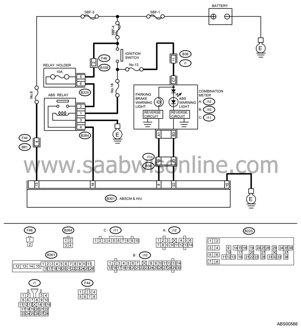
WIRING DIAGRAM:

DATA CHECK Vehicle Diagnostic Interface.
Select {Current Data Display & Save} in Vehicle Diagnostic Interface.Read the condition of “ABS warning light”.
Is “ON” indicated?
| Yes |
| No |
CHECK WIRING HARNESS.
Measure the resistance between ABSCM connector and combination meter connector.Connector & terminal
(i10) No. 3 — (B301) No. 22:
Is the resistance less than 0.5 Ω?
| Yes |
| No |
Repair harness and connector between ABSCM&H/U and combination meter connector.
CHECK POOR CONTACT IN CONNECTOR.
Is there poor contact in ABSCM connector and combination meter connector?
| Yes |
Repair the connector.
| No |
Check the combination meter.


