Cylinder head
| Cylinder head |
(in-car)
| To remove |
| Important | ||
|
The cylinder head must be removed only if the engine is at room temperature. |
||
| 1. |
Place the car on a lift, lay out wing covers, disconnect the battery cables, remove the battery and open the expansion tank cap.

|
|
| 2. |
Raise the car, remove the lower engine cover and the front right wheel.
|
|
| 3. |
Place a receptacle under the radiator and engine. Open the radiator drain plug.
|
|
| 4. |
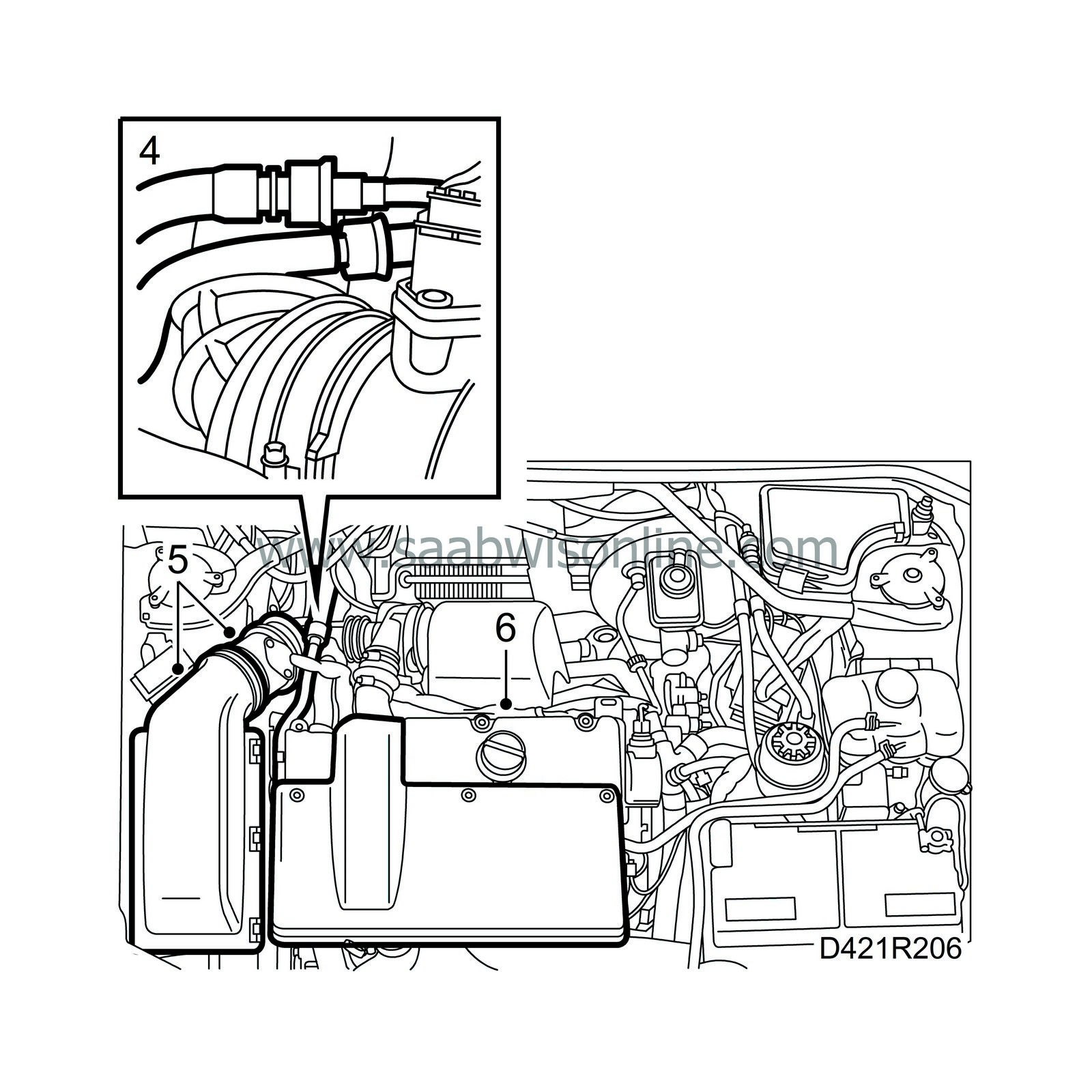
Lower the car, split the fuel lines with tool 83 95 261 and seal them.
|
|
| 5. |
Remove the air cleaner with mass air flow sensor and hoses from the turbocharger and camshaft cover.
|
|
| 6. |
Remove the engine cover.
|
|
| 8. |
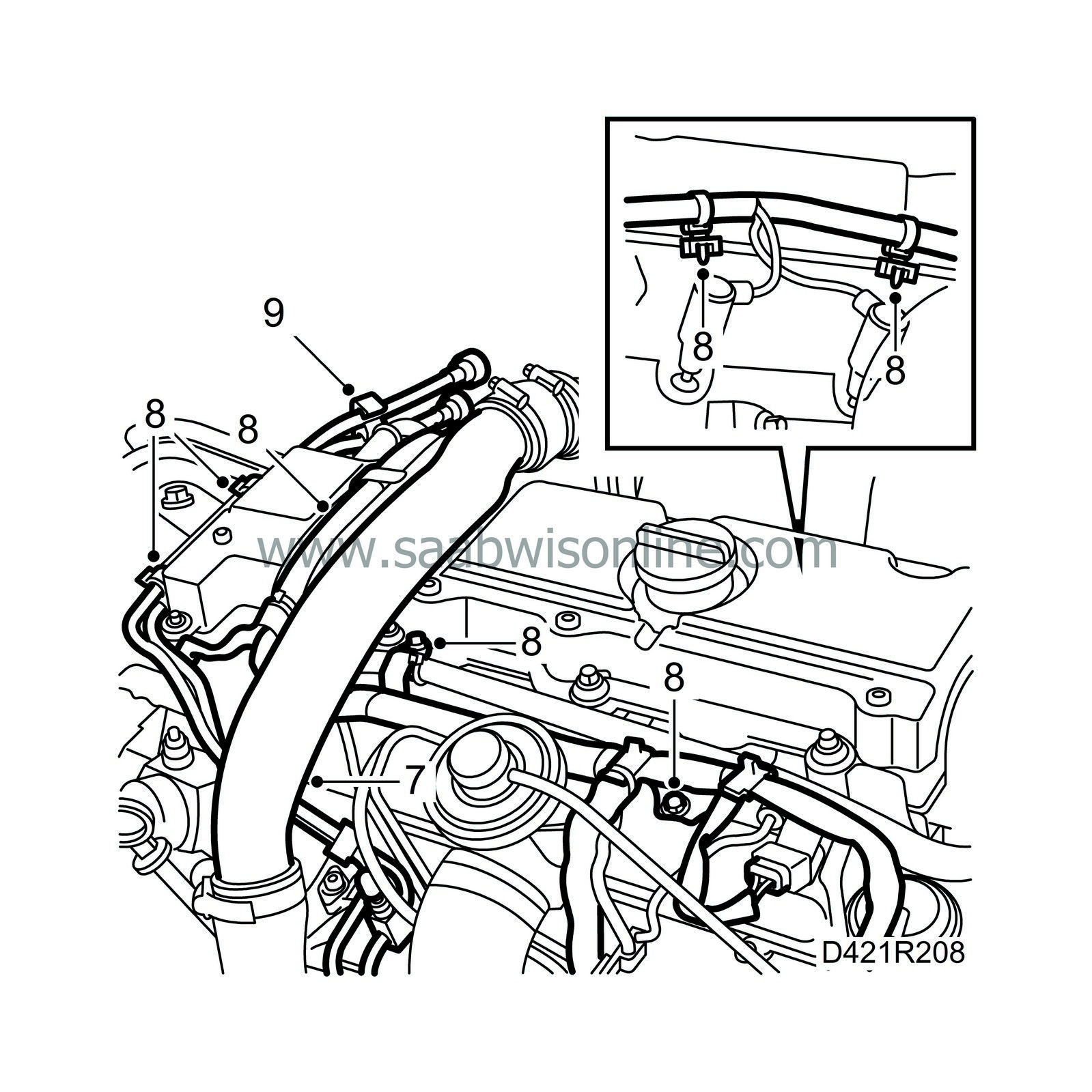
Remove both wiring harness ducts from the cylinder head, cut all the fasteners and disconnect the fuel lines from the camshaft cover.
|
|
| 9. |
Detach the fuel lines from the bracket and remove the wiring harness with bracket from the engine mounting.
|
|
| 10. |
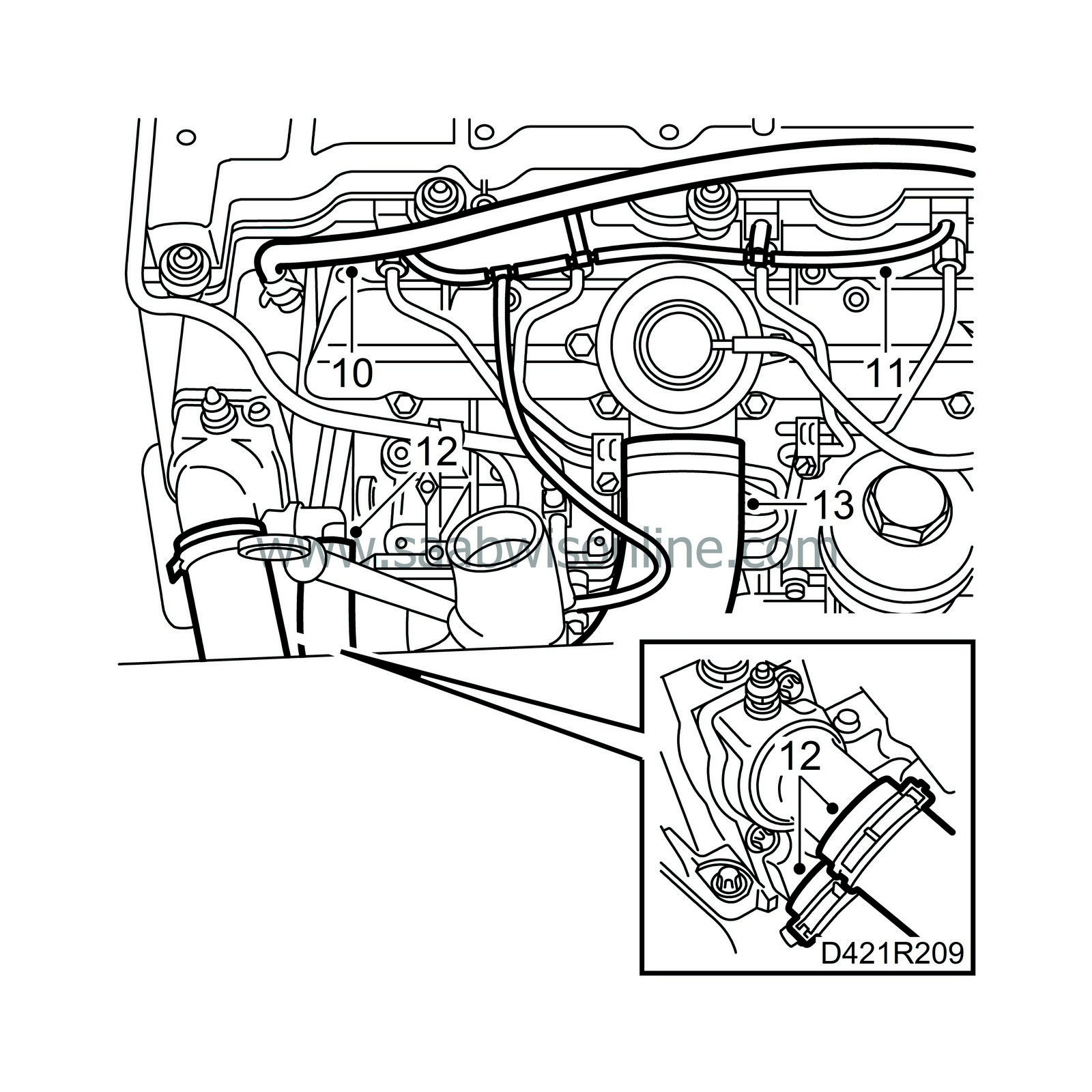
Detach the vent hose from the thermostat housing and put it to one side.
|
|
| 11. |
Pull off the fuel return hoses.
|
|
| 12. |
Remove the hoses from the thermostat housing.
|
|
| 13. |
Detach the hose from the intake manifold, seal the hose and put it to one side.
|
|
| 14. |
Detach the fuel lines from the fuel distribution pump and put them to one side.

|
|
| 15. |
Note the position of the fuel rails and their clamps, mark the rails and remove them.
|
|
| 16. |
Remove the vacuum hose from the swirl throttle control valve.
|
|
| 17. |
Remove the vacuum hose from the EGR valve.
|
|
| 18. |
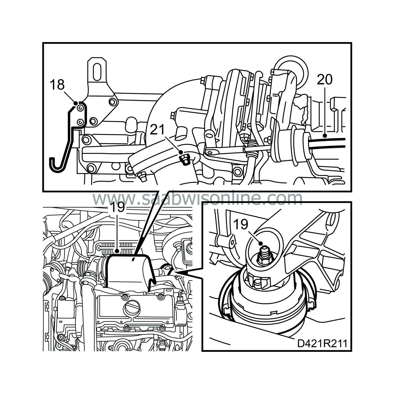
Detach the hook for the coolant hose from the rear lifting eye.
|
|
| 19. |
Remove the heat shields over the turbocharger and the exhaust manifold, and undo the nut on the rear engine mounting.
|
|
| 20. |
Pull off the vacuum hose from the wastegate.
|
|
| 21. |
Remove the rear nut from the front exhaust pipe connection to the turbocharger.
|
|
| 22. |
Cover the generator to protect it against coolant spill and detach the coolant hose from the generator bracket.

|
|
| 23. |
Detach the vacuum hose to the brake servo and the vacuum hose connected to the underside of the vacuum pump.
|
|
| 24. |
Undo the four vacuum pump retaining bolts and carefully lift away the vacuum pump and its adapter.
|
||||||||||
| 25. |
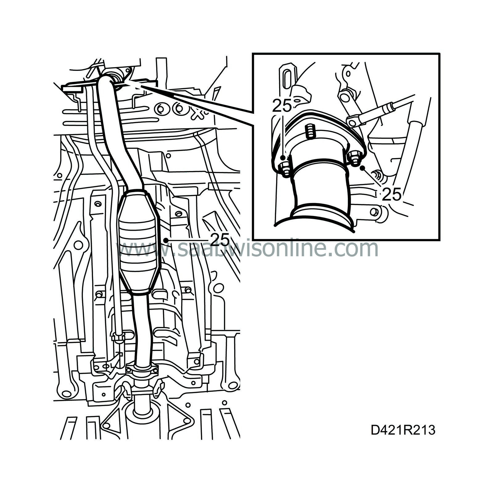
Raise the car and detach the front part of the exhaust pipe from the turbocharger.
|
|
| 26. |
Remove the top bolt on the exhaust manifold support and loosen the bottom bolt so that the support can be twisted aside.

|
|
| 27. |
Detach both turbocharger oil pipes from the cylinder block and seal the pipes.
|
|
| 28. |
Relieve the tension on the belt tensioner by turning it anticlockwise (towards the rear of the car) with a 19 mm wrench and lift off the belt.

|
|
| 29. |
Remove the belt tensioner.
|
|
| 30. |
Remove the crankshaft position sensor with O-ring and lower the car.
|
|
| 31. |
Place a jack with a wooden block on top under the oil sump and carefully lift the engine to take the weight off the right-hand engine mounting.
|
||||||||||
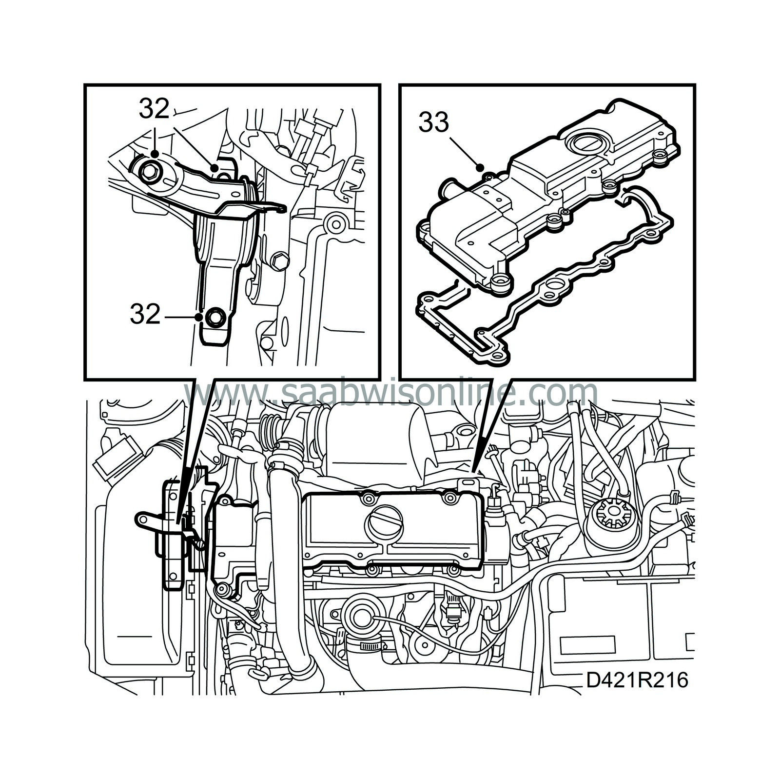
| 32. |
Remove the right-hand engine mounting from the engine and the body.
|
|
| 33. |
Remove the camshaft cover.
|
|
| 34. |
Remove the bolts on the cover, carefully insert a putty knife behind the cover and prise it off.

|
||||||||||
| 35. |
Turn the crankshaft two revolutions with the centre bolt on the pulley until it nearly reaches the mark for top dead centre in cylinder 1. Make sure both cam lobes for cylinder 1 are pointing upwards.
|
|
| 36. |
Position inspection gauge 83 95 352 inside the hole for the crankshaft position sensor. Press the tool slightly inwards at the same time as the crankshaft is turned to the zero mark. The tool will then enter a recess in the crankshaft and secure it.
|
|
| 37. |
Make sure the marks on the crankshaft pulley and the timing cover are aligned. The arrow on the single cam chain sprocket on the fuel distribution pump must be aligned with the recess in the pump. Position inspection gauge 83 95 337 in the hole.
|
|
| 38. |
Remove all inspection gauges.
|
|
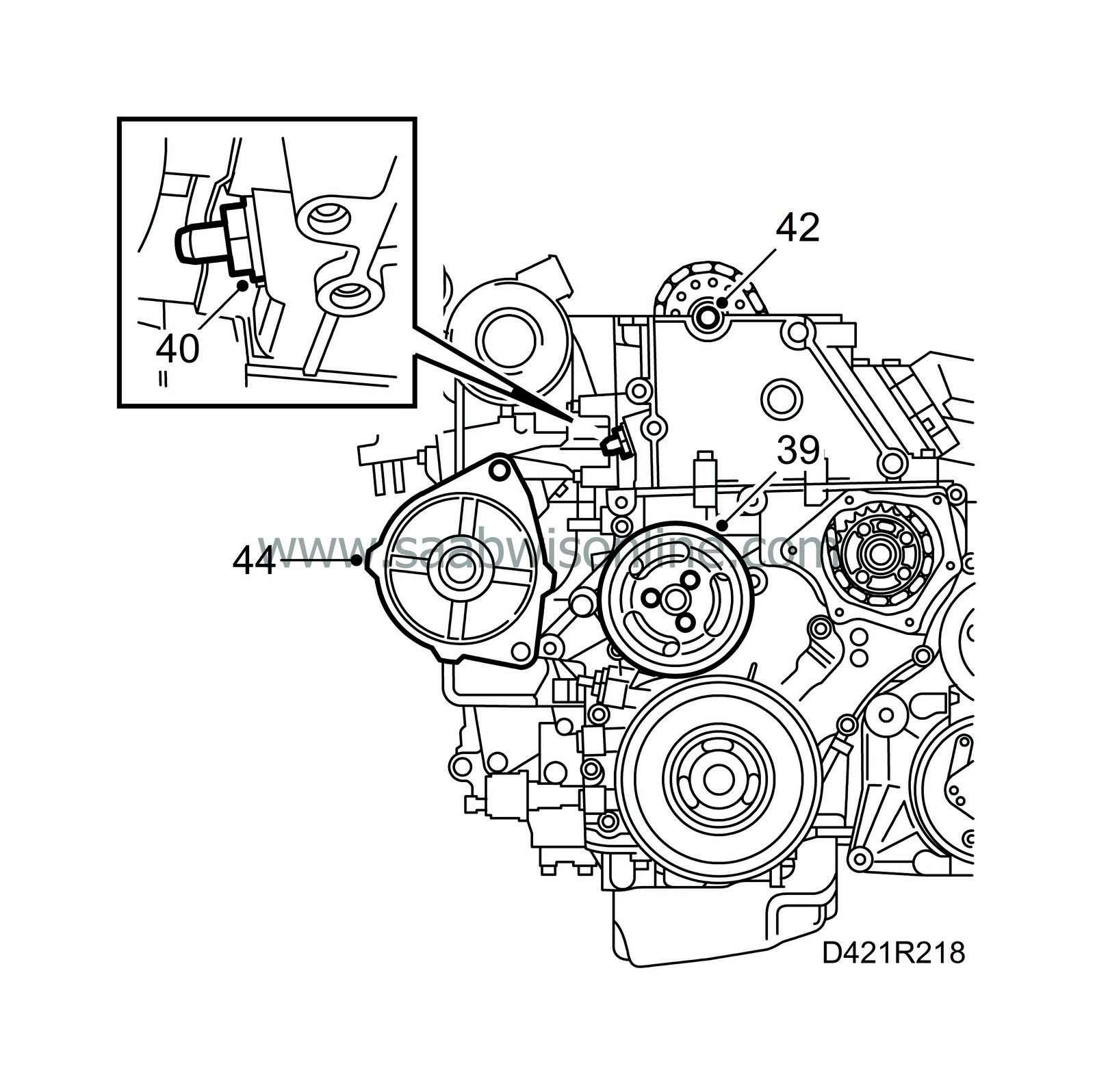
| 39. |
Remove the coolant pump pulley and the coolant pump.
|
|
| 40. |
Remove the upper timing chain tensioner.
|
|
| 41. |
Attach a long cable tie to the timing chain. This is to be used as a handle.
|
|
| 42. |
Remove the camshaft sprocket using an open wrench in the hexagonal recess on the camshaft as support.
|
|
| 43. |
Carefully place the chain to one side.
|
|
| 44. |
Remove the upper generator mounting bolt and loosen the bottom one so that the generator can be rotated downwards.
|
|
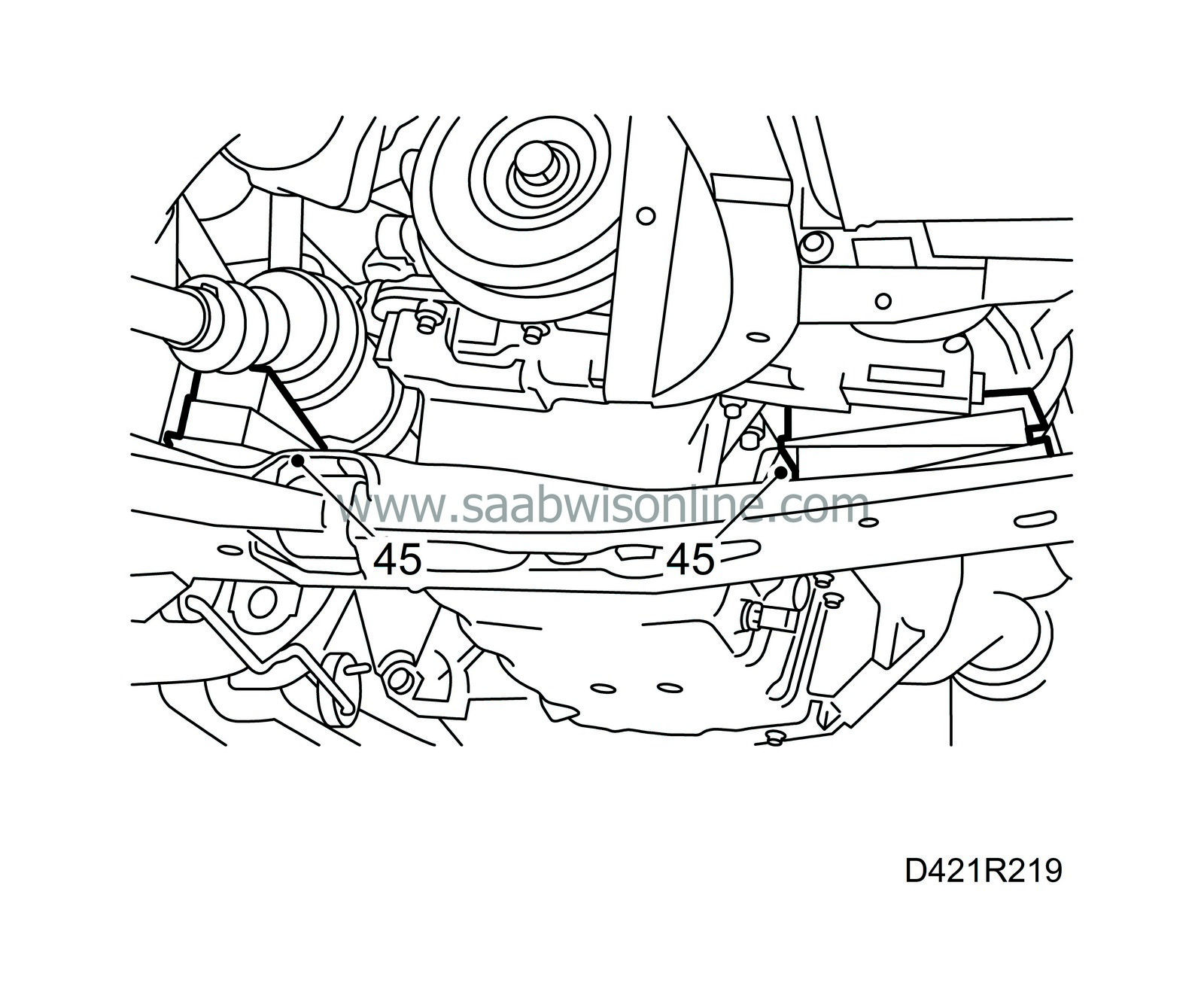
| 45. |
Place wedges (83 95 238) between the bottom part of the power steering pump bracket and the subframe and between the universal joint and the subframe so that the engine is properly supported. Lower the engine and remove the jack.
|
|
| 46. |
Undo the four bolts securing the cylinder head to the timing cover.

|
||||||||||
| 47. |
Remove the cylinder head by undoing the bolts in the illustrated order. Lift the cylinder head
straight up
and place it in such a way so the fuel injectors, glow plugs or valves are not damaged.
|
|
| To fit |

| 1. |
Remove any gasket remains from the sealing surfaces on the cylinder head.
|
|
| 2. |
Check with a steel rule that the sealing surfaces on the cylinder head and cylinder block are flat and not damaged.
|
|
| 3. |
Fit a new gasket with the same thickness marking as the old gasket to the cylinder head. (1 groove = 1.3 mm, 2 grooves = 1.4 mm gasket thickness.)
|
|
| 4. |
Position inspection gauge 83 95 386 on the camshaft and cylinder head. The camshaft can be turned slightly if necessary with an open wrench in the hexagonal recess on the camshaft at the same time as the gauge is put into the correct position.
|
|
| 5. |
Position the cylinder head on the cylinder block while pulling the timing chain up to its correct position.
|
|
| 6. |
Tighten the cylinder head with new bolts in the order shown in the illustration.
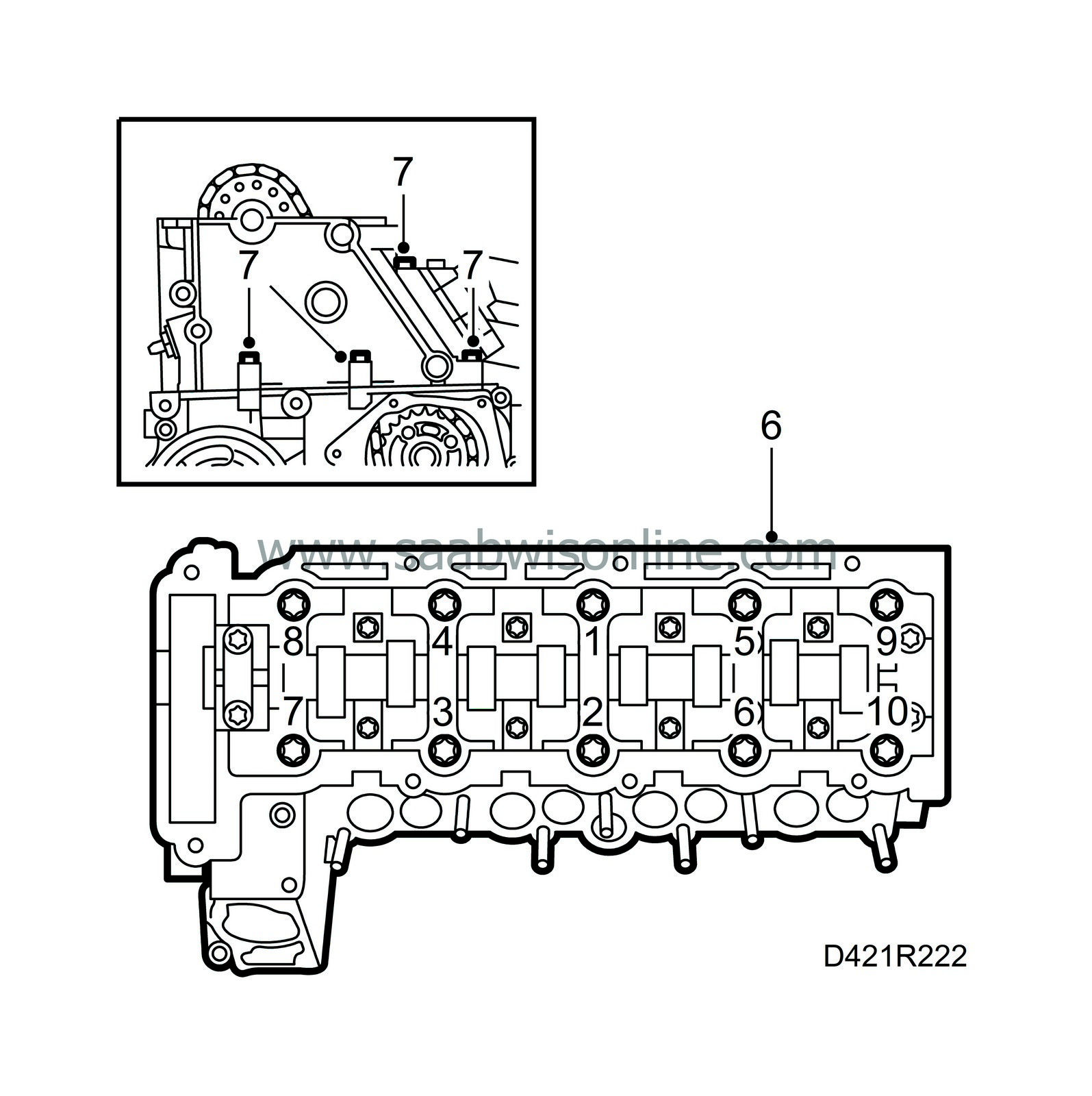
Tightening torques Stage I: 25 Nm (18.5 lbf ft) Stage II: 65° Stage III: 65° Stage IV: 65° Stage V: 65° |
||||||||||
| 7. |
Tighten the bolts on the timing cover as previously fitted.
Tightening torque 20 Nm (15 lbf ft). |
|
| 8. |
Place a jack with wood block under the oil sump, carefully raise the engine and remove the wedges between the engine and the subframe.
|
|
| 9. |
Refit the generator.

Tightening torque 35 Nm (26 lbf ft). |
|
| 10. |
Lift up the timing chain and position the camshaft gear so that it runs freely on the camshaft, and fit it with a new bolt. Tighten by hand.
|
||||||||||
| 11. |
Position inspection gauge 83 95 337 in the fuel distribution pump recess.
|
|
| 12. |
Fit the adapter for the timing chain adjuster 83 95 394 on the camshaft sprocket and the timing chain adjuster on the cylinder head.

|
|
| 13. |
Secure the position of the adapter on the camshaft sprocket by turning it slightly anticlockwise with a ratchet handle. Tighten the adjuster screw on the tool.
|
||||||||||
| 14. |
Tighten the bolt for the camshaft sprocket using an open wrench in the hexagonal recess on the camshaft as support.
Tightening torque 90 Nm (66.5 lbf ft) + 60°. |
|
| 15. |
Fit the chain tensioner for the upper timing chain with a new gasket.
Tightening torque 60 Nm (44 lbf ft). |
|
| 16. |
Remove all tools and gauges.
|
|
| 17. |
Turn the crankshaft two revolutions with the centre bolt on the pulley until it nearly reaches the mark for top dead centre in cylinder 1. Make sure both cam lobes for cylinder 1 are pointing upwards.

|
|
| 18. |
Position inspection gauge 83 95 352 inside the hole for the crankshaft position sensor. Press the tool slightly inwards at the same time as the crankshaft is turned to the zero mark. The tool will then enter a recess in the crankshaft and secure it.
|
|
| 19. |
Make sure the marks on the crankshaft pulley and the timing cover are aligned. The arrow on the single cam chain sprocket on the fuel distribution pump must also be aligned with the recess in the pump.
|
|
| 20. |
Position inspection gauge 83 95 337 in the fuel distribution pump recess. If the gauge does not fit, the engine valve timing must be adjusted. See
 .
.
|
|
| 21. |
Position inspection gauge 83 95 386 to the camshaft and cylinder head. If the gauge does not fit, the engine valve timing must be adjusted. See
 .
.
|
|
| 22. |
Fit the coolant pump and pulley.
Tightening torque 20 Nm (15 lbf ft). |
|
| 23. |
Remove all inspection gauges.
|
|
| 24. |
Clean any gasket remains from the sealing surfaces on the camshaft cover.

|
|
| 25. |
Position a new gasket on the camshaft cover. There are sleeves on the bolts on which the gasket fits.
|
|
| 26. |
Apply sealing compound 87 81 841 to the sealing surface, see illustration.
|
|
| 27. |
Position the transmission cover on the cylinder head and tighten the bolts.
Tightening torque 8 Nm (6 lbf ft). |
|
| 28. |
Cover the opening in the timing cover with a lint-free cloth and remove any remains from the old gasket from the sealing surface. Clean the sealing surface on the cap.

|
|
| 29. |
Apply a bead (approx. 2 mm thick) of silicone sealant to the cap, remove the cloth from the timing cover and fit the cap.
Tightening torque 6 Nm (4.5 lbf ft). |
|
| 30. |
Fit the right-hand engine mounting to the engine.
Tightening torque 47 Nm (35 lbf ft). Carefully lower the engine and remove the jack. |
|
| 31. |
Make sure the engine is suspended evenly and tighten the right-hand engine mounting.
Tightening torque 47 Nm (35 lbf ft). |
|
| 32. |
Apply Molycote 1000 to the turbocharger studs.
|
|
| 33. |
Raise the car and fit the crankshaft position sensor with a new O-ring.
Tightening torque 8 Nm (6 lbf ft). |
|
| 34. |
Fit the belt tensioner, tightening the top bolt first.
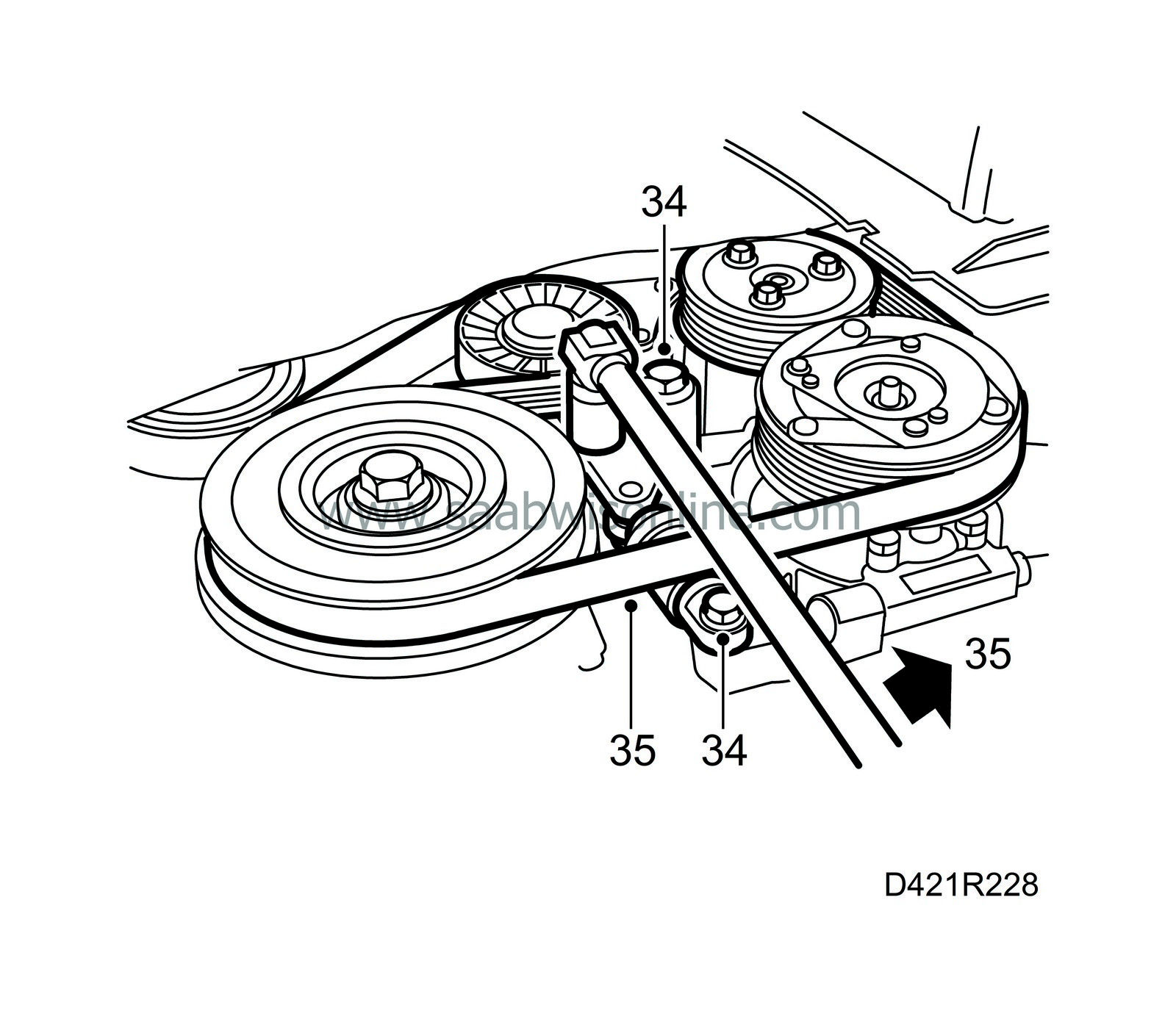
Tightening torque 42 Nm (31 lbf ft). Tighten the bottom bolt. Tightening torque 23 Nm (17 lbf ft). |
|
| 35. |
Fit the multigroove V-belt on all the pulleys. Relieve the tension on the belt tensioner by turning it anticlockwise (towards the rear of the car) with a 19 mm wrench and fit the belt on its pulley. Make sure the belt is positioned correctly on all the pulleys.
|
|
| 36. |
Connect the turbocharger oil return pipe to the cylinder block.

Tightening torque 30 Nm (22 lbf ft). |
|
| 37. |
Connect the turbocharger oil delivery pipe to the cylinder block.
Tightening torque 20 Nm (15 lbf ft). |
|
| 38. |
Put the exhaust manifold support back in place and tighten the screws.
Tightening torque 25 Nm (18.5 lbf ft). |
|
| 39. |
Position the front part of the exhaust pipe with a new gasket and fit new nuts.
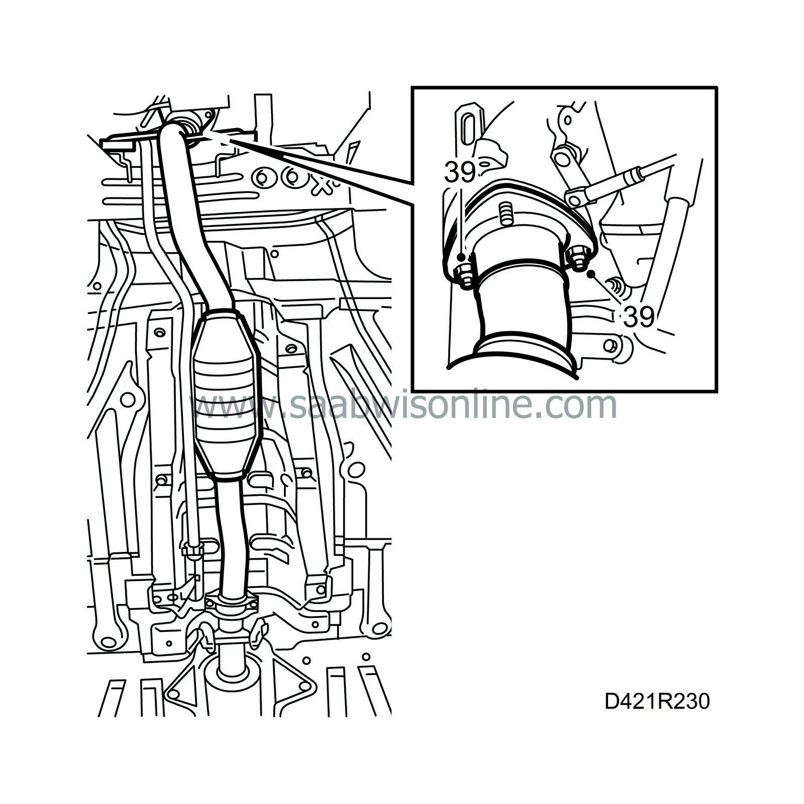
|
|
| 40. |
Fit the front exhaust pipe loosely, making sure it is not strained, and tighten it to the turbocharger.
Tightening torque 25 Nm (18.5 lbf ft). |
|
| 41. |
Refit the lower engine cover and the wheel.
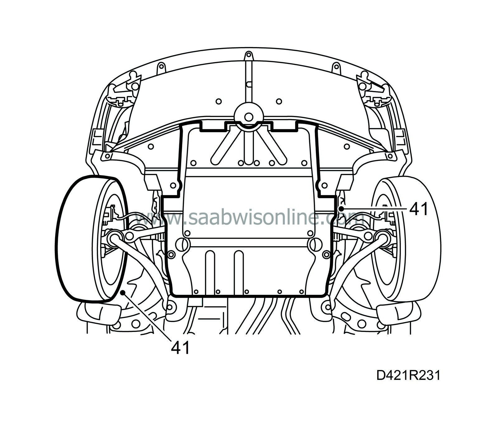
Tightening torque 110 Nm (81 lbf ft). Lower the car to the floor. |
|
| 42. |
Tighten the remaining nuts between the turbocharger and the front exhaust pipe.
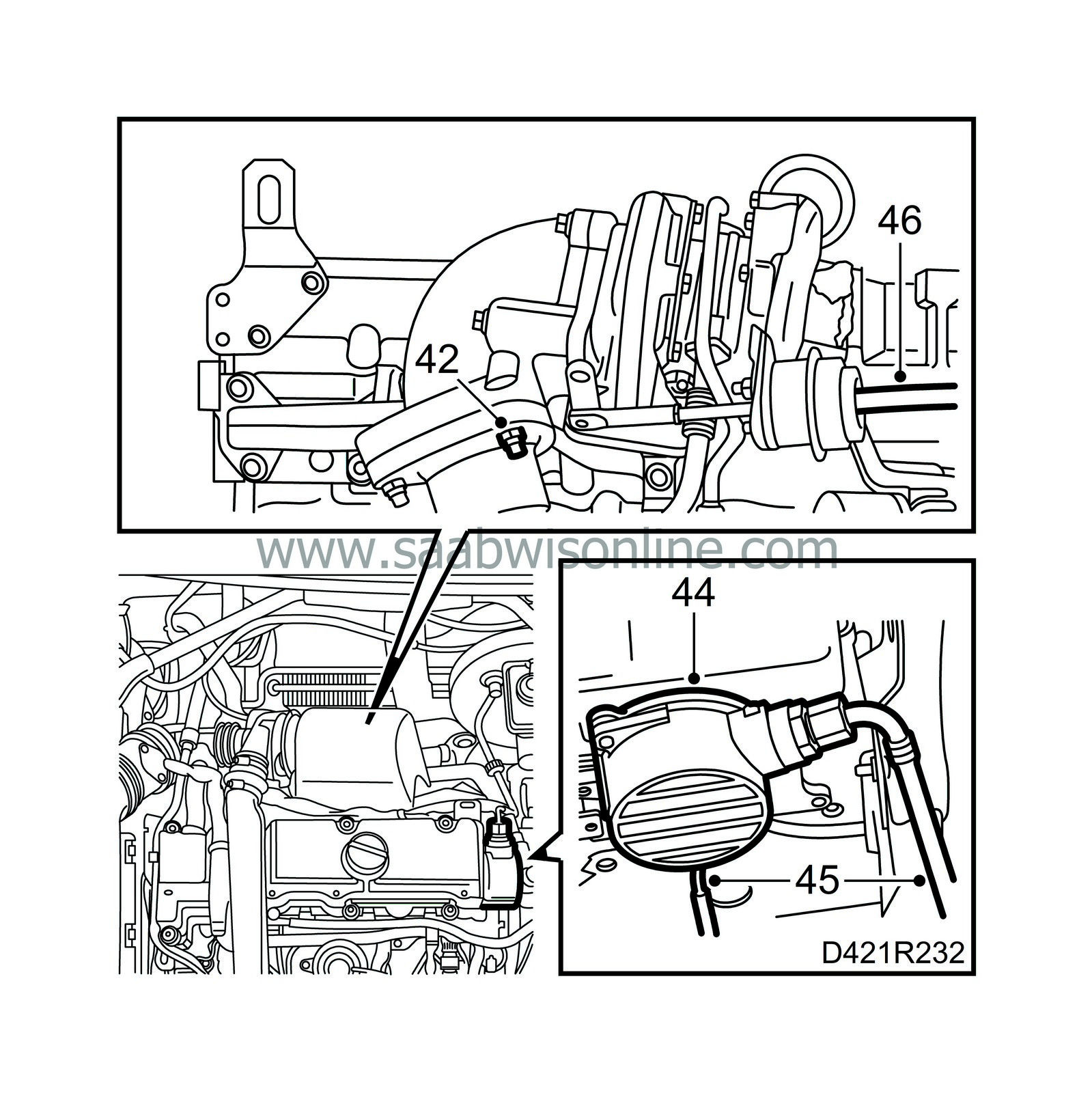
Tightening torque 25 Nm (18.5 lbf ft). |
|
| 43. |
Clean the sealing surfaces on the vacuum pump.
|
|
| 44. |
Fit a new gasket on the vacuum pump and fit the pump together with the adapter.
Tightening torque 8 Nm (6 lbf ft). |
||||||||||
| 45. |
Connect the vacuum hose for the brake servo to the vacuum pump.
Tightening torque 18 Nm (13 lbf ft). Connect the vacuum hose to the bottom of the vacuum pump. |
|
| 46. |
Connect the vacuum hose to the wastegate vacuum box.
|
|
| 47. |
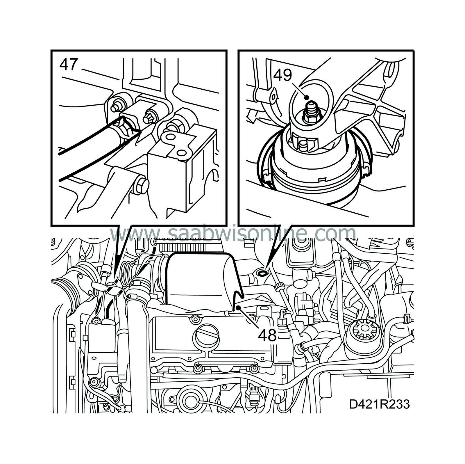
Attach the coolant hose to the generator bracket.
|
|
| 48. |
Refit the heat shields over the turbocharger and the exhaust manifold.
|
|
| 49. |
Tighten the nut on the rear engine mounting.
Tightening torque 47 Nm (35 lbf ft). |
|
| 50. |
Fit the hook for the coolant hose on the rear lifting eye.
|
|
| 51. |
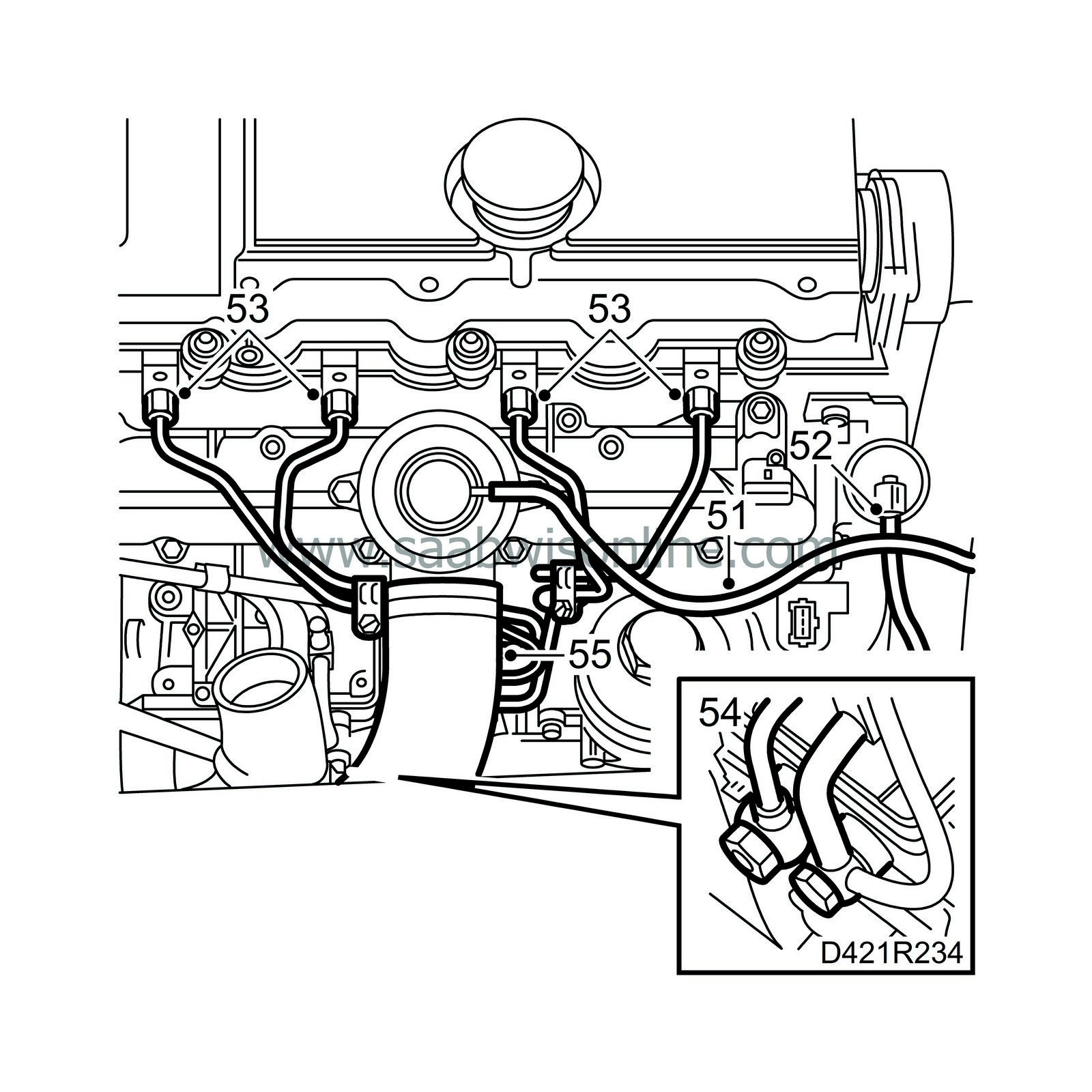
Connect the vacuum hose to the EGR valve.
|
|
| 52. |
Connect the vacuum hose to the swirl throttle control valve.
|
|
| 53. |
Attach the fuel rails with clamps in their original positions.
Tightening torque 25 Nm (18.5 lbf ft). |
|
| 54. |
Connect the fuel lines to the fuel distribution pump with new seals.
Tightening torque 25 Nm (18.5 lbf ft).
|
||||||||||
| 55. |
Connect the hose to the intake manifold.
|
|
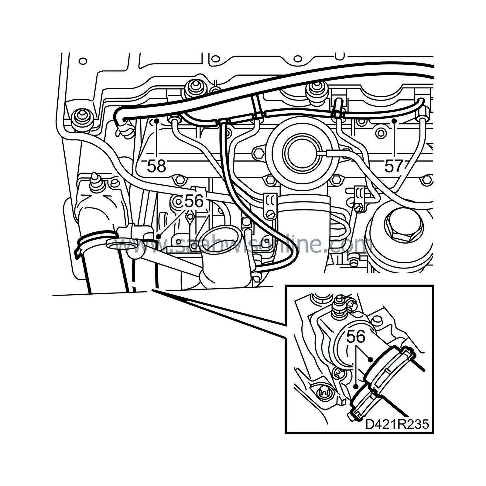
| 56. |
Connect the hoses to the thermostat housing.
|
|
| 57. |
Connect the fuel return hoses to the fuel bridges. Remove the connection at the fuel pump and connect pressure/vacuum pump 30 14 883. Pump up a vacuum of 750 mbar and wait 1 minute. Make sure the dial indicator on the tool has not moved.
If a leak is detected, the fuel bridges must be inspected individually. Remove the fuel bridge with the leak, change the seal and refit the fuel bridge. Make sure there are no more leaks. |
|
| 58. |
Connect the vent hose to the thermostat housing.
|
|
| 59. |
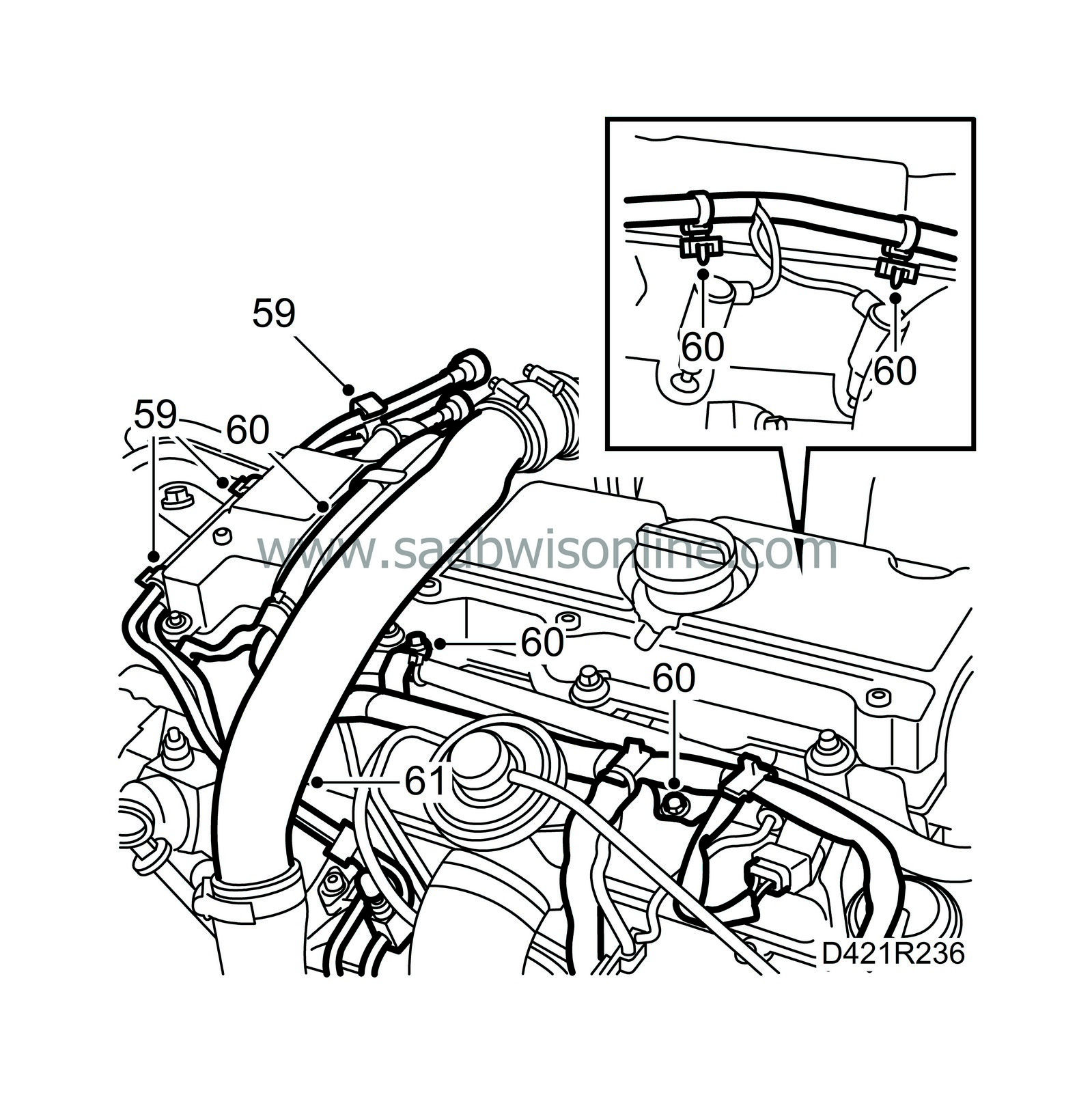
Fit the wiring harness bracket to the engine mounting and press the fuel lines on the bracket.
|
|
| 60. |
Fit the wiring harness ducts to the cylinder head, plug in all the connectors and secure the wiring harness.
|
|
| 61. |
Refit the turbo delivery pipe with connecting hose and neck. Lubricate the O-ring with vaseline.
|
|
| 62. |
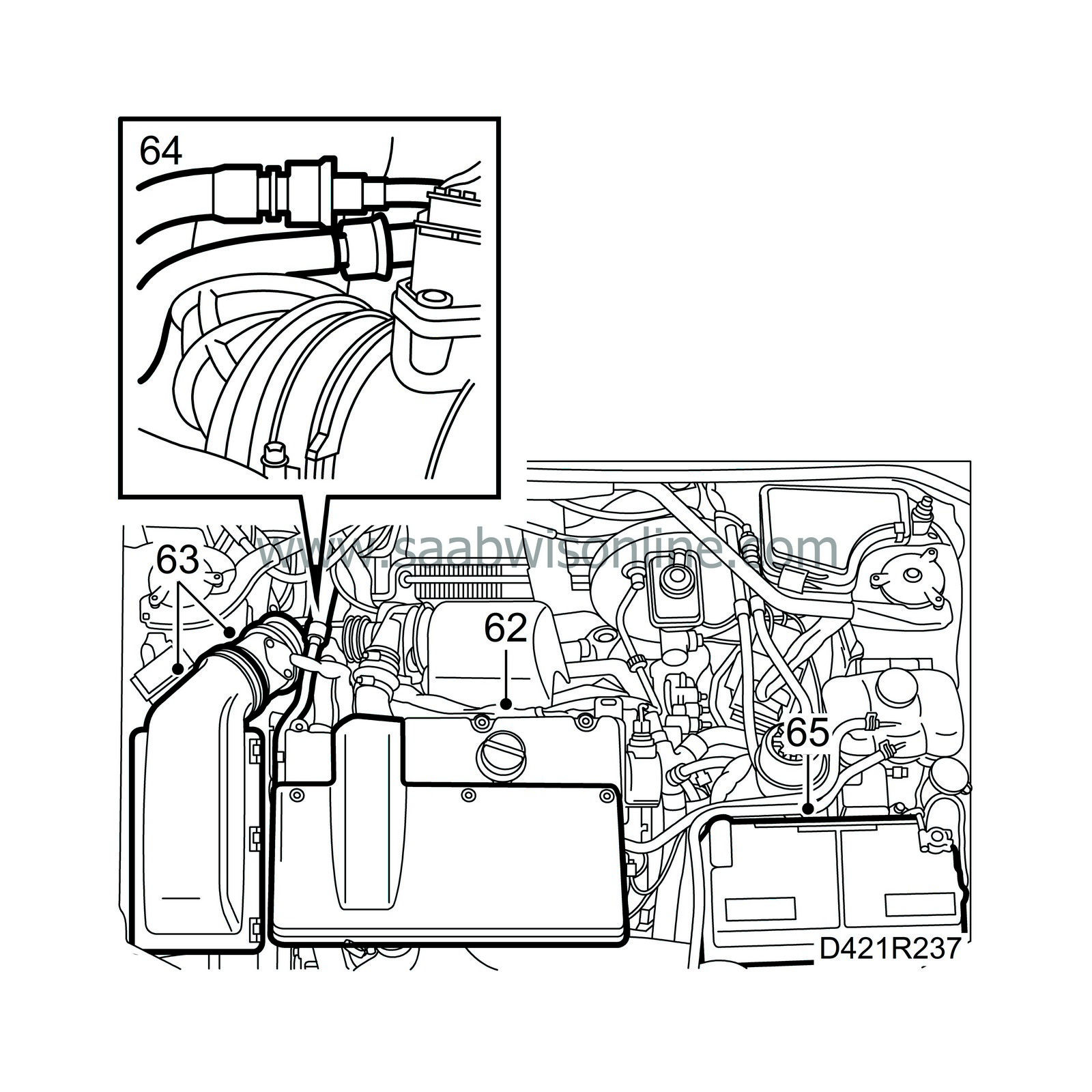
Refit the engine cover.
|
|
| 63. |
Refit the air cleaner with mass air flow sensor and hoses.
|
|
| 64. |
Connect the fuel lines.
|
|
| 65. |
Fit the battery and connect the cables.
|
|
| 66. |
Top up engine oil according to specifications, see
 .
.
|
|
| 67. |
Fill with coolant, check the integrity of the system and bleed it as follows:
Connect exhaust hoses to both the engine exhaust system and the auxiliary heater exhaust system and start the engine. Start the parking heater using the diagnostics instrument. The parking heater stops when the engine has reached a temperature of 80°C or if the parking heater menu is exited. Make sure there is a continuous flow of coolant in the hose from the thermostat housing to the expansion tank. Run the engine until the thermostat has opened. |
|||||||
| 68. |
Restore the engine bay to its original condition.
|
|
| 69. |
Adjust the clock in the car and press 5 times on the remote control lock/unlock button.
|
|

 Warning

