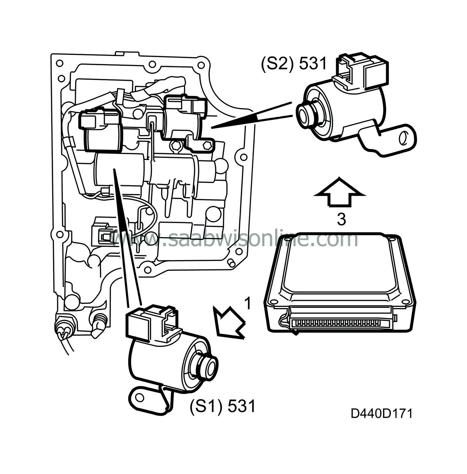
Solenoid valves, S1 and S2, for shifting
| Solenoid valves, S1 and S2, for shifting |
Solenoid valves S1 and S2 are located in the valve housing which is mounted on the transmission casing. The two solenoid valves control the hydraulic shifting valves by opening and closing the return flow providing system pressure for the relevant shifting valve.
The solenoids are grounded via their casing directly to the valve housing and the control module activates the relevant solenoid by supplying it with battery voltage (B+). A solenoid not supplied with current is closed. Solenoid S1 is connected to control module pin 1 and solenoid S2 is connected to control module pin 3.
The power supply is governed by the control module, which gives a signal for shifting up or down depending on speed, throttle position and the current driving program.
Operation of the solenoids (S1 and S2) in regard to the selector lever positions is as follows:


|
Selector lever position
|
S1
|
S2
|
|
1
|
OFF (0 V)
|
ON (B+)
|
|
2
|
ON (B+)
|
ON (B+)
|
|
3
|
ON (B+)
|
OFF (0 V)
|
|
4
|
OFF (0 V)
|
OFF (0 V)
|
The nominal resistance of the solenoid windings is 13 ohms. Solenoids S1 and S2 are identical (same type).
Diagnostics
A short-circuit between solenoid S1 and ground will generate diagnostic trouble code P1852.An open circuit (S1) will generate diagnostic trouble code P1853.
A short-circuit between solenoid S2 and ground will generate diagnostic trouble code P1857.
An open circuit (S2) will generate diagnostic trouble code P1858.
The transmission goes into limp-home mode.


