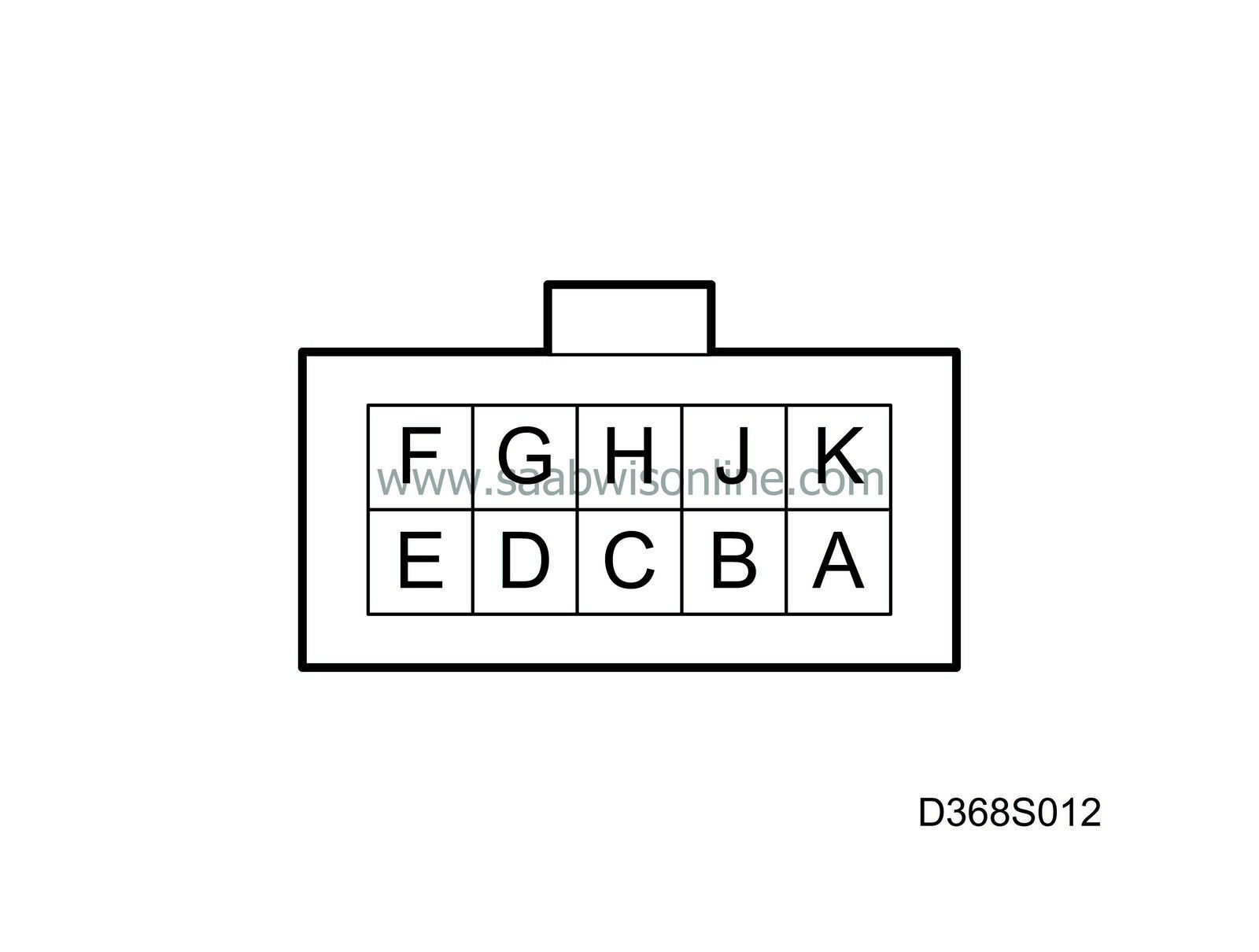
Test readings, control module connections
|
|
Test readings, control module connections
|
Test readings and directions for measuring signals and levels on the cruise control module are given in the following pages.


|
•
|
Note the test conditions and use common sense when assessing the test result.
|
|
•
|
The test readings presented are with the ignition ON unless otherwise stated.
|
|
•
|
First check that the control module has a power supply and is grounded.
|
|
•
|
Then check all sensor inputs and signals from other systems.
|
|
•
|
Finally, check the control module outputs. Remember that the test reading does not tell us whether the actuator is in working order.
|
|
•
|
If any reading is not OK, consult the wiring diagram to trace the leads, connectors or components which should be checked more thoroughly.
|
|
•
|
The specified test readings refer to those obtained with a calibrated Fluke 88/97.
|
|
•
|
The test readings % (+) and ms (+) indicate the pulse ratio and pulse duration of the signal. A test instrument for measuring pulse ratio and pulse duration must be used. The (+) sign indicates a positive trigger pulse, TRIG+.
|
The pins are identified by both a number and a letter. Note that Pin I does not exist.

|
Pin
|
Lead colour
|
Component/Function
|
In/Out
|
Test conditions
|
Across
|
Test reading
|
See
|
1 (A)
|
GN
|
Switch A, cruise control
|
In
|
Hold the ON/OFF switch in the On position. Ignition switch ON.
|
1-5
|
B+
|

|
2 (B)
|
GN/GY
|
Switch B, cruise control
|
In
|
Hold the ON/OFF switch in the On position. Ignition switch ON.
|
2-5
|
B+
|

|
3 (C)
|
GY
|
Switch C, cruise control
|
In
|
Hold the ON/OFF switch in the On position. Ignition switch ON.
|
3-5
|
B+
|

|
4 (D)
|
YE/GN
|
Pedal switches
|
|
|
|
|
|
|
|
Pedal switch, brakes
|
In
|
Automatic transmission, selector lever in D, 1, 2, 3
Pedal released
Pedal depressed
|
4-5
|
B+
0 V
|

|
|
|
Pedal switch, brakes
|
In
|
Manual
Pedal released
Pedal depressed
|
4-5
|
B+
0 V
|

|
|
|
Pedal switch. clutch
|
In
|
Manual
Pedal released
Pedal depressed
|
4-5
|
B+
0 V
|

|
5 (E)
|
BK
|
Power ground
|
In
|
Always
|
5-B+
5-B-
|
B+
<0.5 V
|

|
6 (F)
|
BN/WH
|
Ignition +54
|
In
|
Ignition on
|
6-5
B+-6
|
B+
<0.5 V
|

|
7 (G)
|
VT
|
Brake lights switch
|
In
|
Pedal depressed
Pedal released
|
7-5
|
B+
0 V
|

|
8 (H)
|
BN/GY
|
CRUISE indicator lamp
|
Out
|
Lamp out
Lamp on
|
8-5
|
0 V
B+
|

|
9 (J)
|
BU/GN
or BU
|
Communication with
Trionic/Motronic
|
Out
|
Cruise control inactive
Cruise control active
|
6-9
|
approx. 10 V
0 V
|

|
10 (K)
|
BK/GN
|
Vehicle speed signal from the ABS control module
|
In
|
LH front wheel spinning
|
10-5
|
The multimeter reading should alternate between about 0 V and B+
|

|


