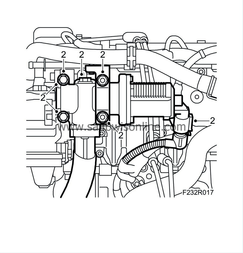
Intake manifold/seal, Z19DTH
| Intake manifold/seal, Z19DTH |
| Important | ||
|
Always use wing covers when working in the engine bay. |
||
| To remove |
| 1. |
Remove
High-pressure pump
.
|
|
| 3. |
Take the cap off the expansion tank to release any pressure.
|
|
| 4. |
Raise the car.
|
|
| 5. |
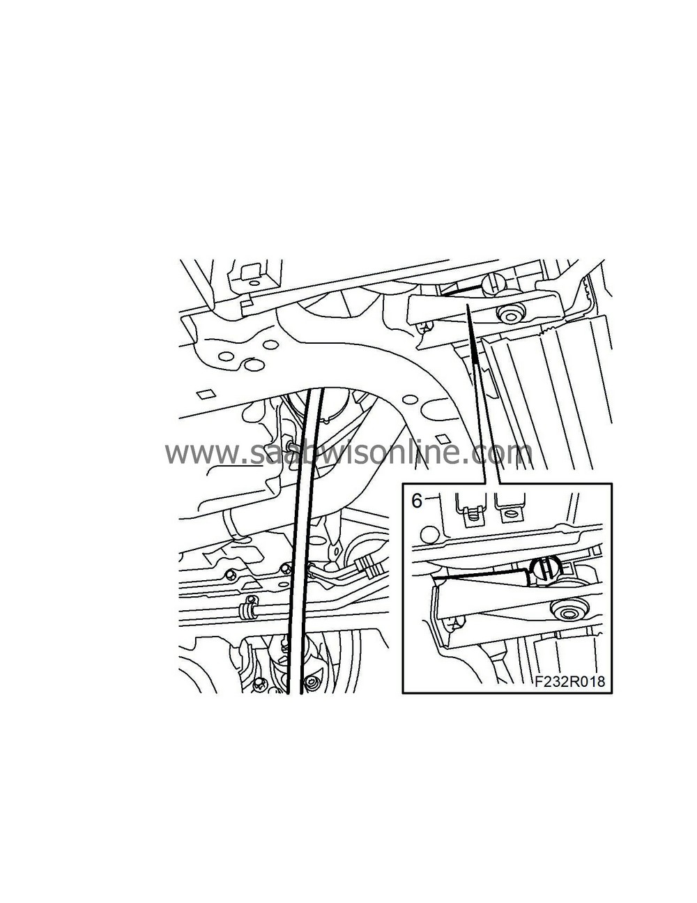
Undo the right-hand part of the front lower cover and bend down.
|
|
| 6. |
Place a receptacle under the radiator, connect a hose to the radiator and drain the coolant. Close the cock and fit the cover.
|
|
| 7. |
Lower the car.
|
|
| 8. |
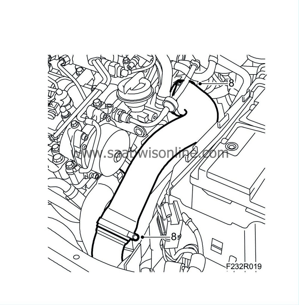
Remove the turbocharger delivery hose from the pipe and throttle body.
|
|
| 9. |
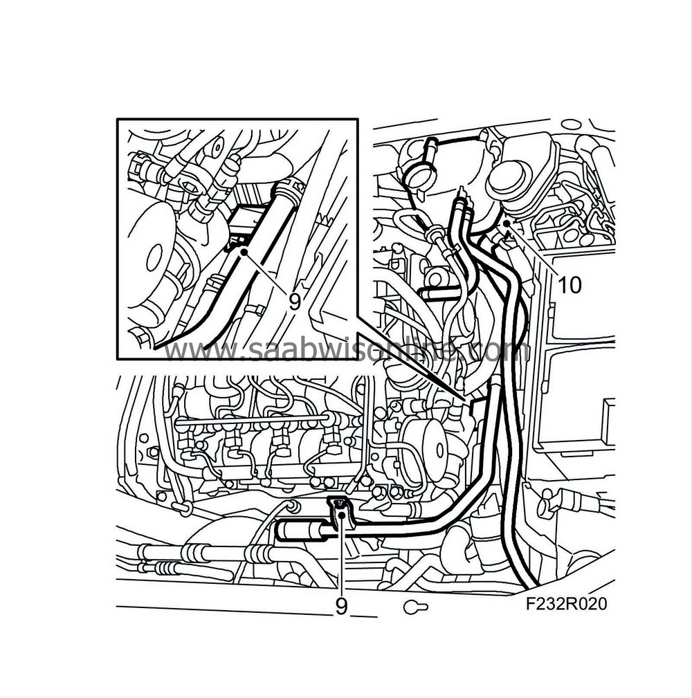
Undo the coolant pipe to the reservoir from the engine.
|
|
| 10. |
Remove the coolant level sensor connector and bend away the reservoir.
|
|
| 11. |
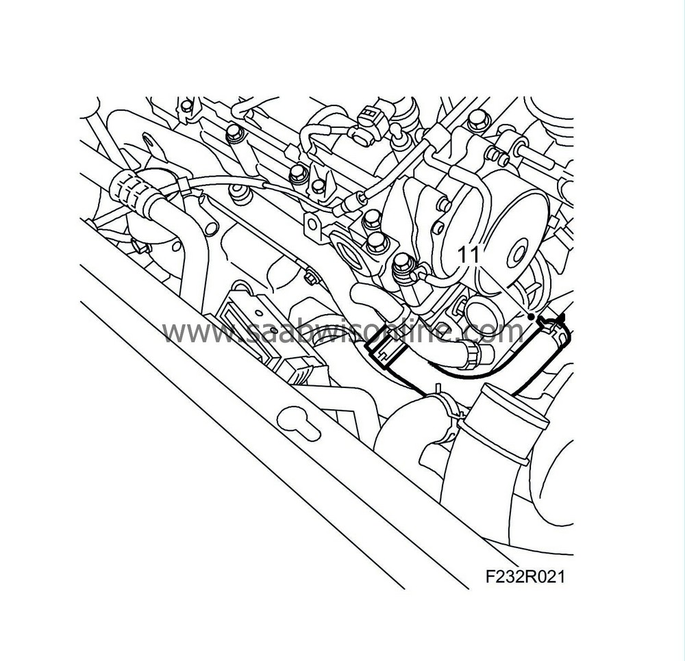
Place a receptacle under the engine to collect the coolant. Remove the coolant hose from the coolant pipe.
|
|
| 12. |
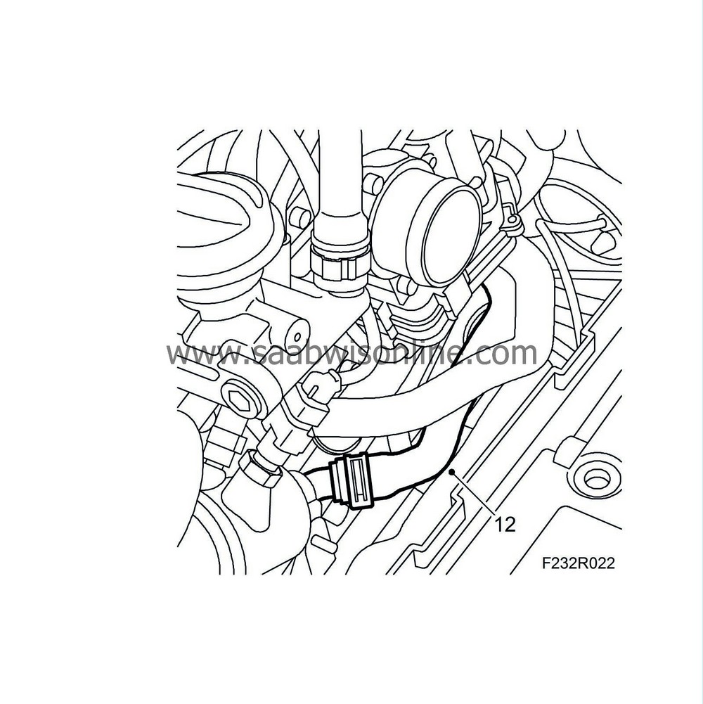
Remove the coolant hose from the thermostat housing.
|
|
| 13. |
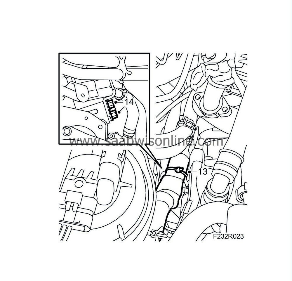
Undo the fixings and press down the wiring harness a little way.
|
|
| 14. |
Remove the nuts holding the coolant pipe to the starter motor bracket. Bend away the pipe slightly to give room for the vacuum reservoir.
|
|
| 15. |
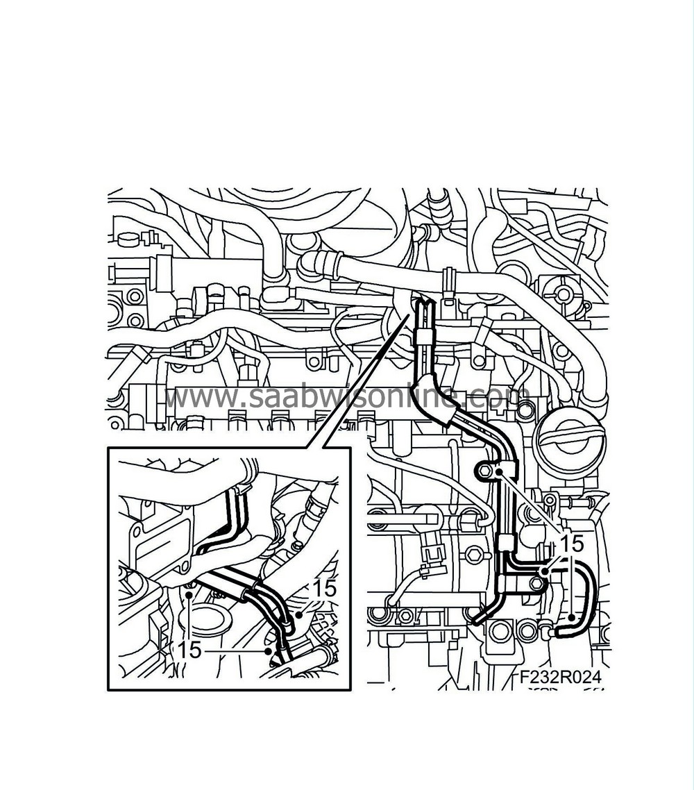
Detach the vacuum hoses from the vacuum reservoir. Remove the vacuum pipe bolts from the camshaft housing and the oil trap bracket.
|
|
| 16. |
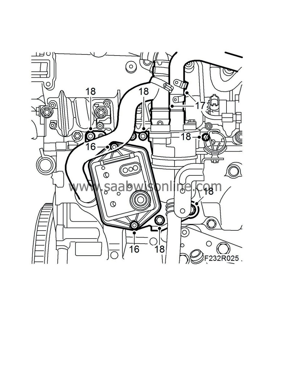
Remove the vacuum container.
|
|
| 17. |
Undo the oil trap upper hoses. The right-hand hose has a quick coupling to the oil trap.
|
|
| 18. |
Remove the nuts and bolts holding the oil trap bracket and bend it aside.
|
|
| 19. |
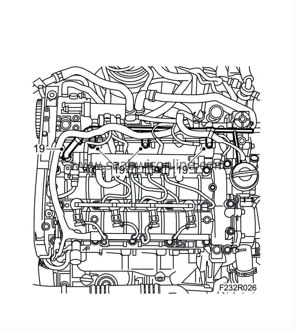
Undo the coolant line from the intake manifold.
|
||||||||||
| 20. |
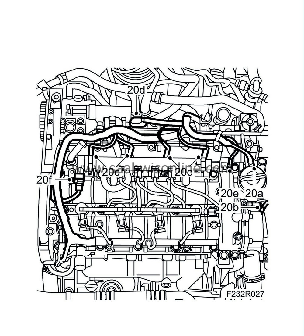
Remove the following connectors:
|
|
| 20.a. |
Throttle body actuator unit (604)
|
| 20.b. |
Coolant temperature sensor (202)
|
| 20.c. |
Glow plug connector (398).
|
| 20.d. |
Intake air sensor (688)
|
| 20.e. |
Fuel pressure sensor (653)
|
| 20.f. |
Fuel pressure control valve (652a)
|
| 21. |
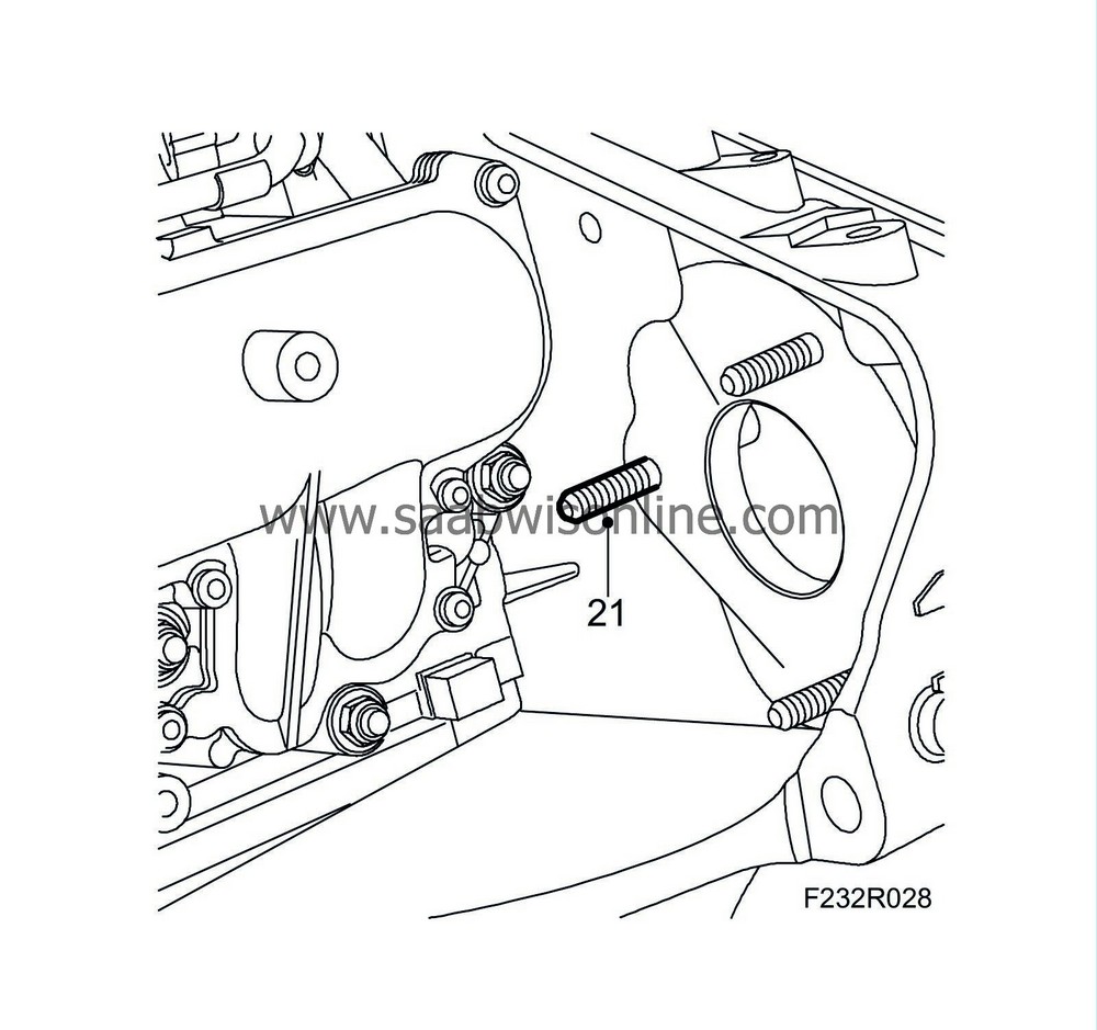
Remove the stud holding the high-pressure pump.
|
|
| 22. |
Remove the connector to the combustion circulation actuator.
|
|
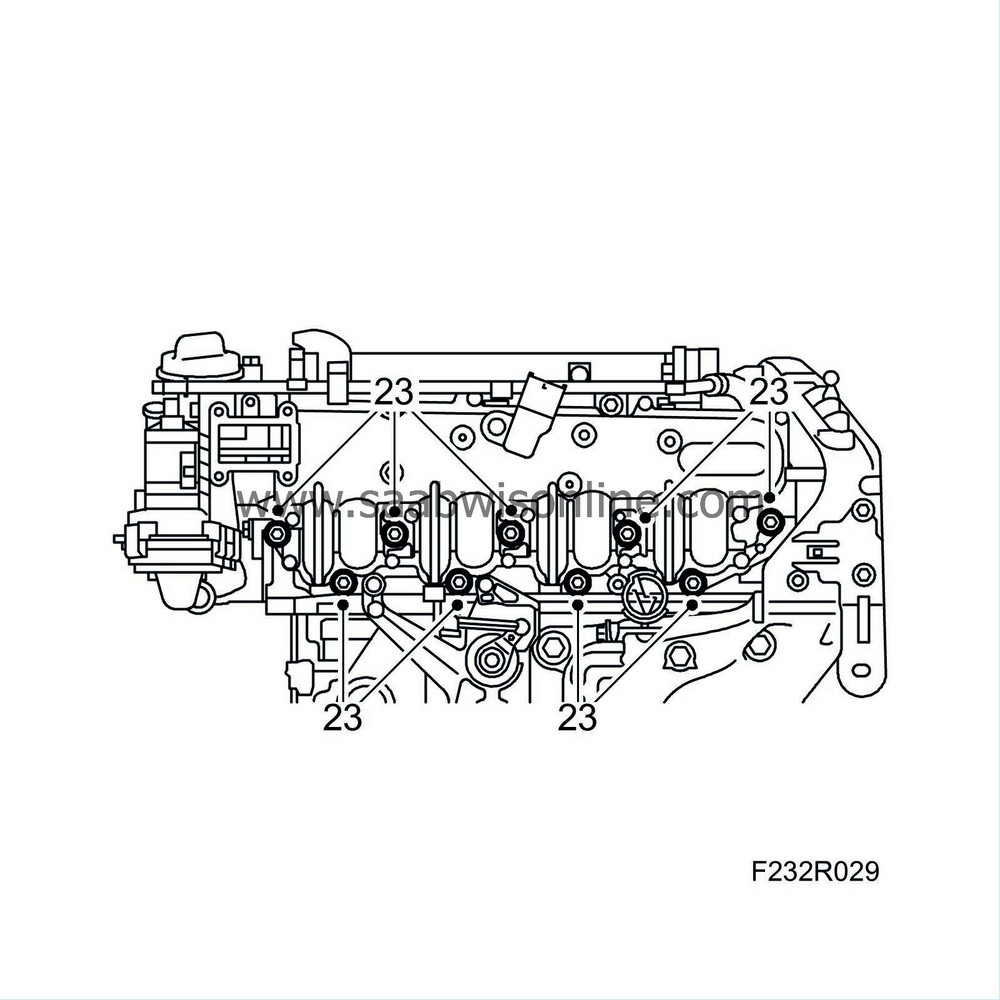
| 23. |
Remove the intake manifold.
|
|
| To fit |
| 1. |
Fit the intake manifold with new seal.
Tightening torque 27 Nm (20 lbf ft). 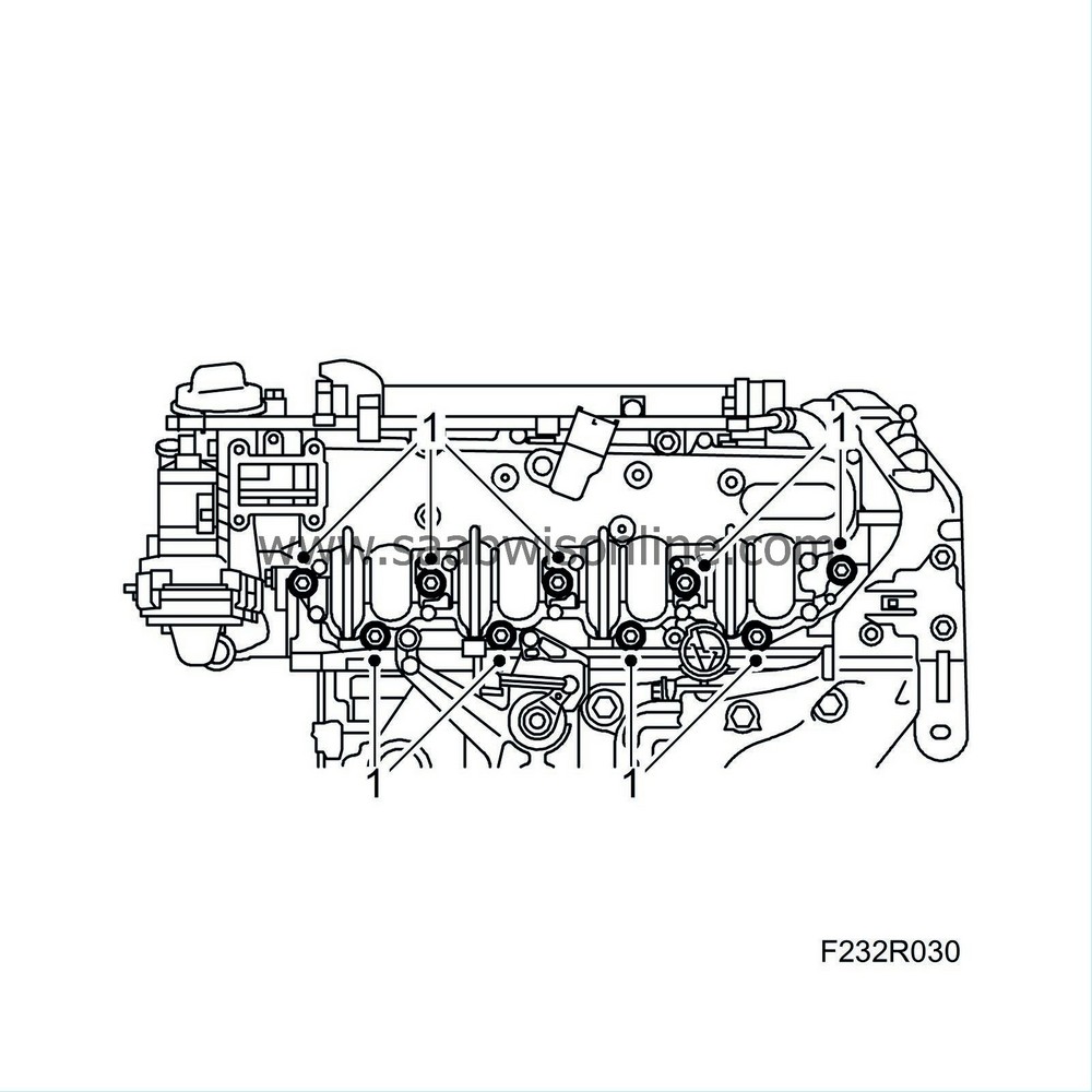
|
|
| 2. |
Connect the combustion circulation actuator.
|
|
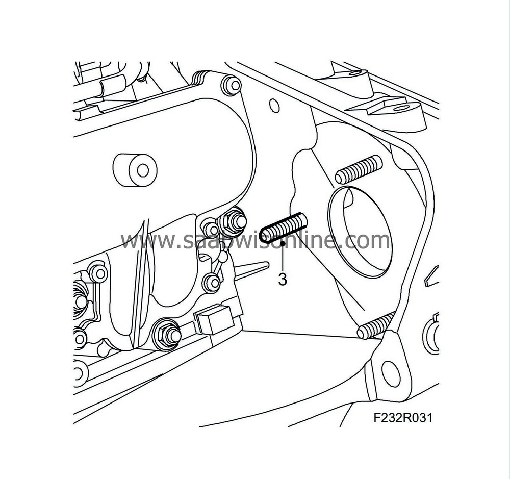
| 3. |
Fit the stud.
|
|
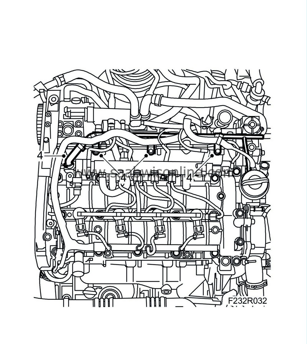
| 4. |
Fit the coolant pipe to the intake manifold.
|
||||||||||
| 5. |
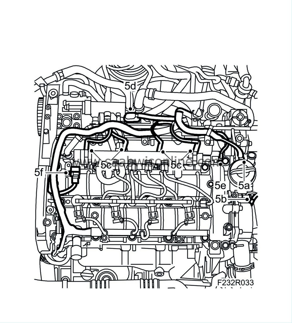
Fit the wiring harness and plug in the following connectors:
|
|
| 5.a. |
Throttle body actuator unit (604)
|
| 5.b. |
Coolant temperature sensor (202)
|
| 5.c. |
Glow plug connector (398).
|
| 5.d. |
Intake air sensor (688)
|
| 5.e. |
Fuel pressure sensor (653)
|
| 5.f. |
Fuel pressure control valve (652a)
|
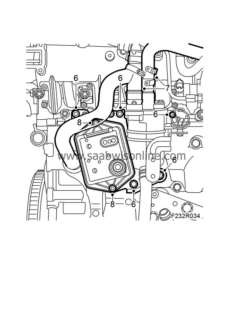
| 6. |
Bend the oil trap bracket back in place and fit the nuts and bolts.
|
|
| 7. |
Fit the oil trap upper hoses.
|
|
| 8. |
Fit the vacuum holder. Note that the narrow hose connection must be located at the top.
|
|
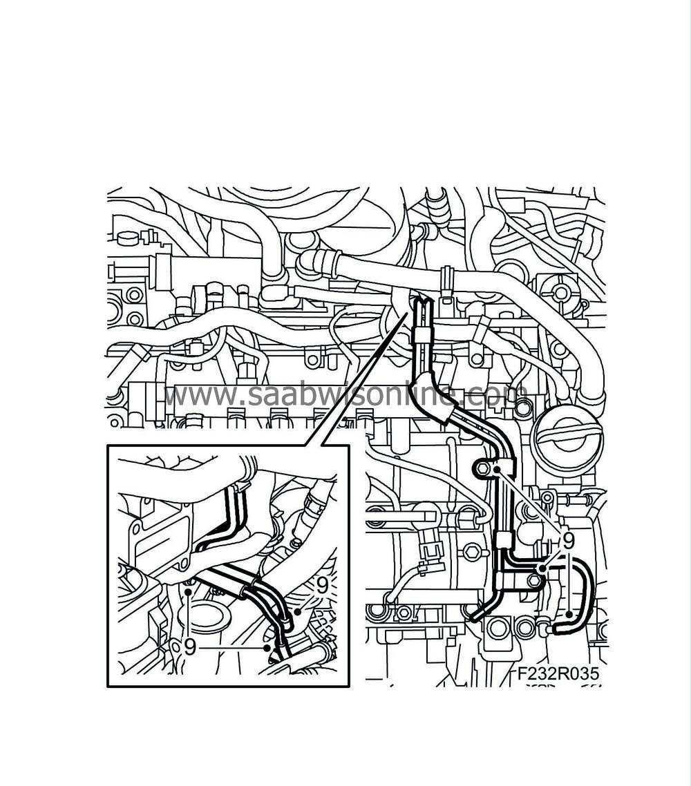
| 9. |
Fit the vacuum pipe on the camshaft housing and connect the hoses to the vacuum reservoir.
|
|
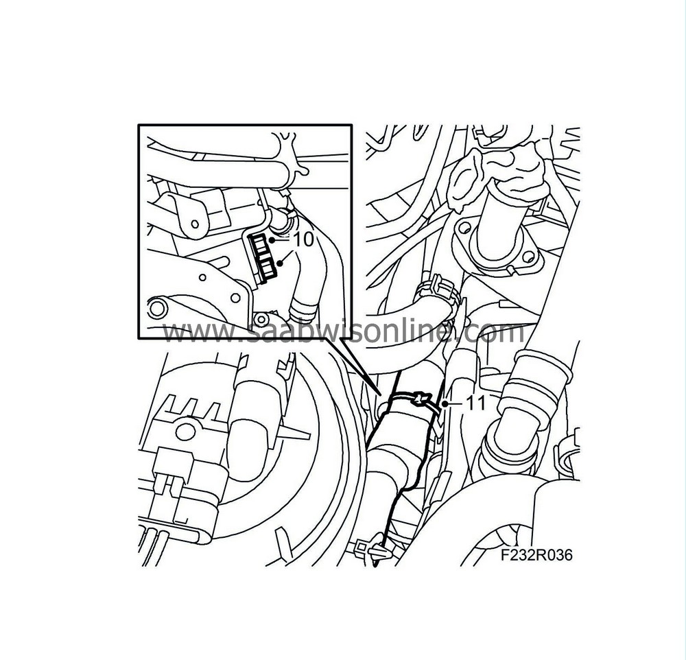
| 10. |
Fit the coolant pipes and wiring harness mountings to the starter motor bracket.
|
|
| 11. |
Fix the wiring harness to the brackets.
|
|
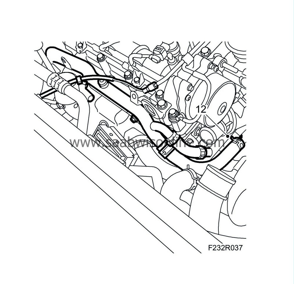
| 12. |
Fit the coolant hose to the coolant pipe.
|
|
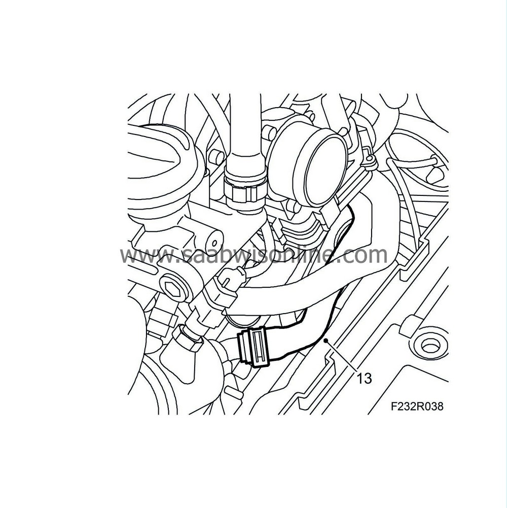
| 13. |
Fit the coolant hose to the thermostat housing.
|
|
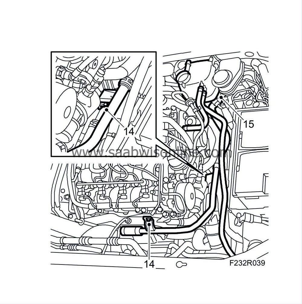
| 14. |
Fit the coolant pipe to the reservoir from the engine.
|
|
| 15. |
Fit the coolant reservoir and connector to the level sensor.
|
||||||||||
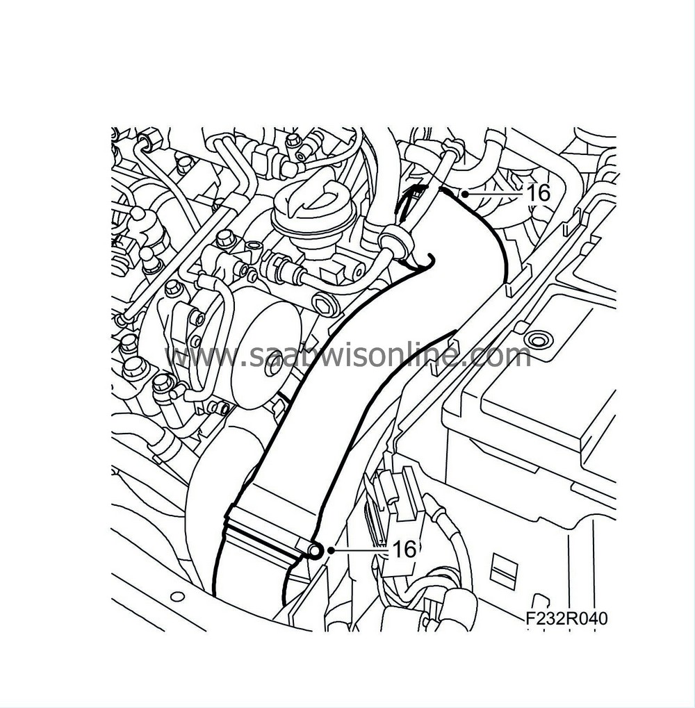
| 16. |
Fit the turbocharger delivery pipe to the turbocharger delivery hose and the throttle body.
|
|
| 17. |
Fit the vacuum lines.
|
|
| 18. |
Fit
High-pressure pump
.
|
|
| 19. |
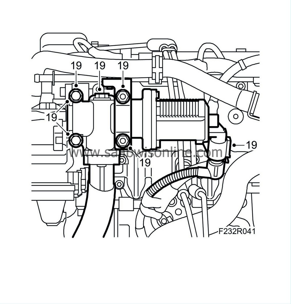
Fit the EGR valve.
|
|
| 20. |
Test pressurise, see
Cooling system, pressure testing
and top up with coolant, see
Filling and bleeding the cooling system
.
|
|
| 21. |
Connect an exhaust hose and start the engine. Check there are no leaks. Connect the diagnostic tool and clear any DTCs.
|
|

 Warning
