Rear camshaft cover
| Rear camshaft cover |
| To remove |
| 1. |
Remove
Heat shield between engine and turbo
.
|
|
| 2. |
Remove the bleeder pipe.

|
|
| 3. |
Release the quick-coupling of the secondary air pipe and put the pipe aside.
|
|
| 4. |
Remove the power steering fluid reservoir's bolt.

|
|
| 5. |
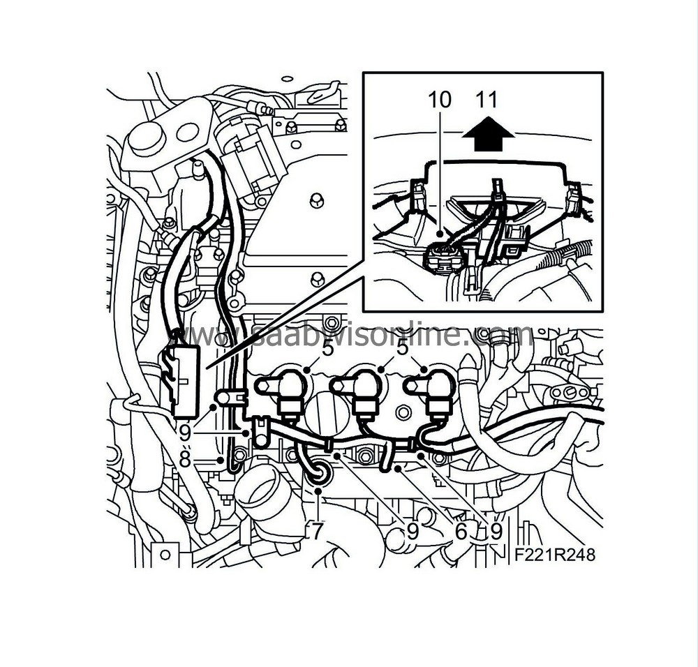
Unplug the connectors from ignition coils 2, 4 and 6.
|
|
| 6. |
Remove the left grounding point.
|
|
| 7. |
Raise the heat shield and unplug the coolant temperature sensor connector.
|
|
| 8. |
Release the right ground cable from the wiring harness.
|
|
| 9. |
Remove the wiring harness from the camshaft cover.
|
|
| 10. |
Unplug the connectors from the camshaft position sensor and the camshaft solenoid valve.
|
|
| 11. |
Raise the wiring harness slightly.
|
|
| 12. |
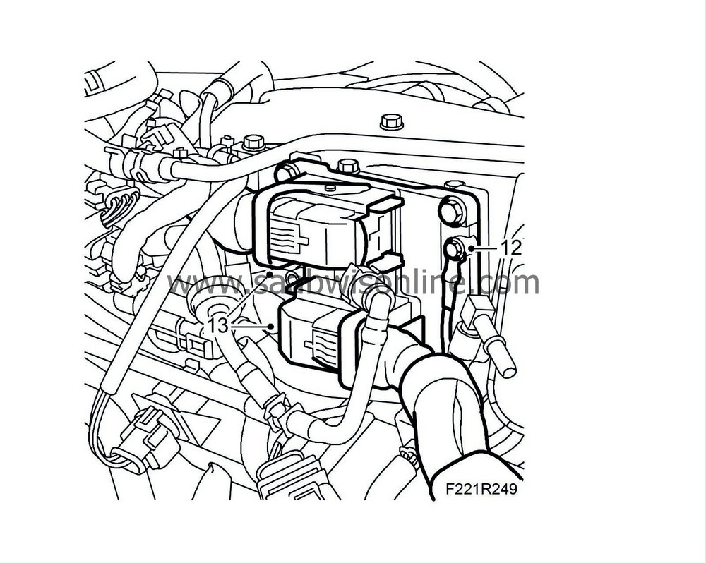
Remove the ground cable of the engine control module.
|
|
| 13. |
Unplug the engine control module connectors (608A and 608B).
|
|
| 14. |
Detach the cable duct from the intake manifold.

|
|
| 15. |
Unplug the atmospheric pressure sensor connectors.
|
|
| 16. |
Detach the corner bracket and move it aside.
|
|
| 17. |
Remove the bolt holding the injector bracket in place and unplug the connector.
|
|
| 18. |
Detach the brake vacuum hose from the intake manifold.

|
|
| 19. |
Detach the crankcase ventilation from the intake manifold.
|
|
| 21. |
Detach the fuel line, wiping up any fuel spill with a cloth.
|
|
| 22. |
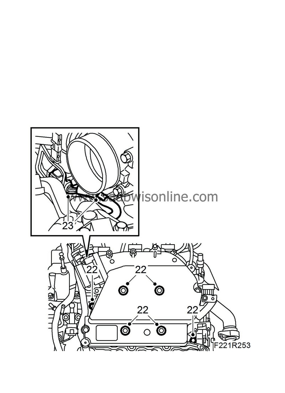
Remove the intake manifold bolts.
|
|
| 23. |
Raise the intake manifold and unplug the throttle body connector. Lift away the intake manifold.
|
|
| 24. |
Remove the gasket and cover the inlet ducts.
|
|
| 25. |
Unplug the connectors from the camshaft position sensor and the camshaft solenoid valve.

|
|
| 26. |
Raise the wiring harness slightly.
|
|
| 27. |
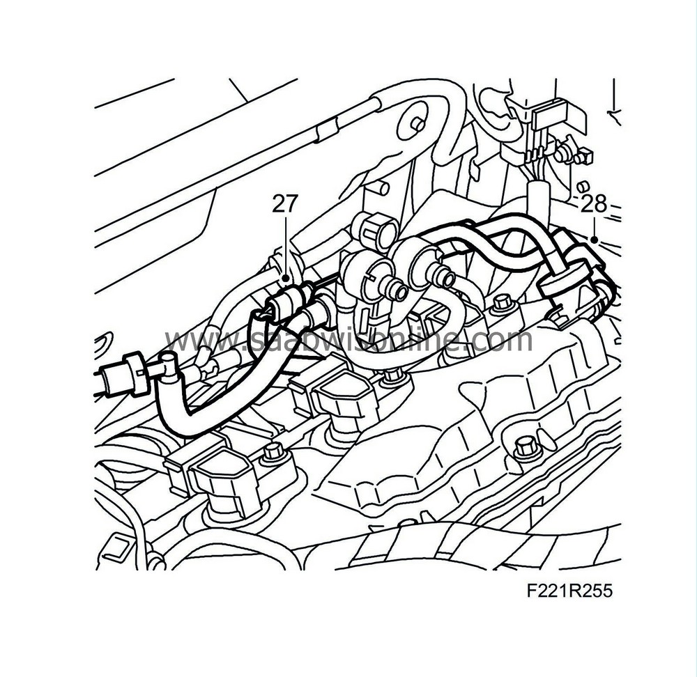
Remove the connector and pipe from the fuel bleeder valve. Lift away the valve.
|
|
| 28. |
Detach the vacuum pipe from the venturi valve.
|
|
| 29. |
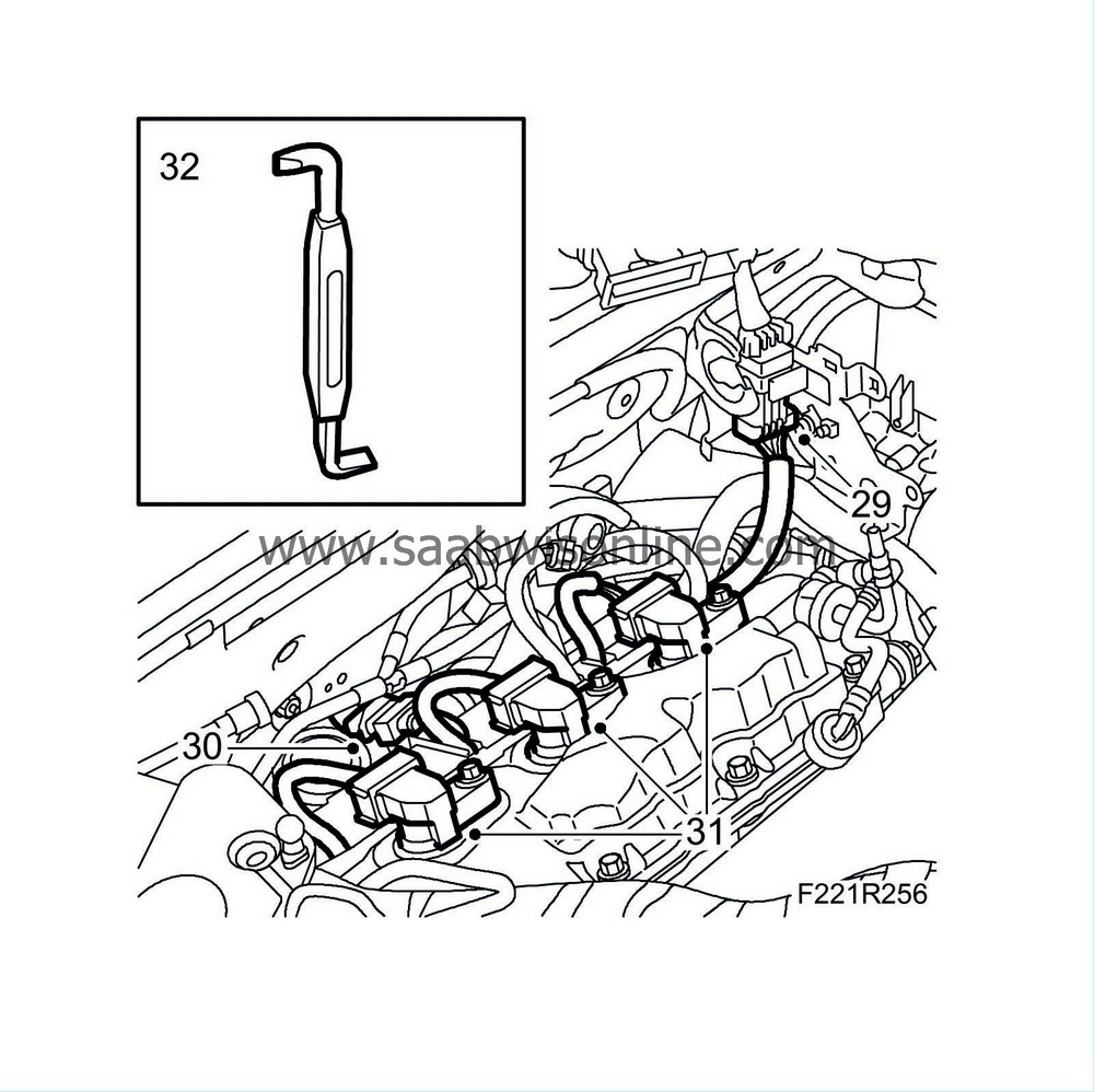
Unplug the 7-pin contact connector.
|
|
| 30. |
Unplug the lower oxygen sensor connector and the connectors of ignition coils 1, 3 and 5.
|
|
| 31. |
Remove ignition coils 1, 3 and 5.
|
|
| 32. |
Remove the rear cable duct from the camshaft cover. Use an angled screwdriver to release the 3 clips from the cable duct. Press the cable duct back toward the bulkhead.
|
|
| 33. |
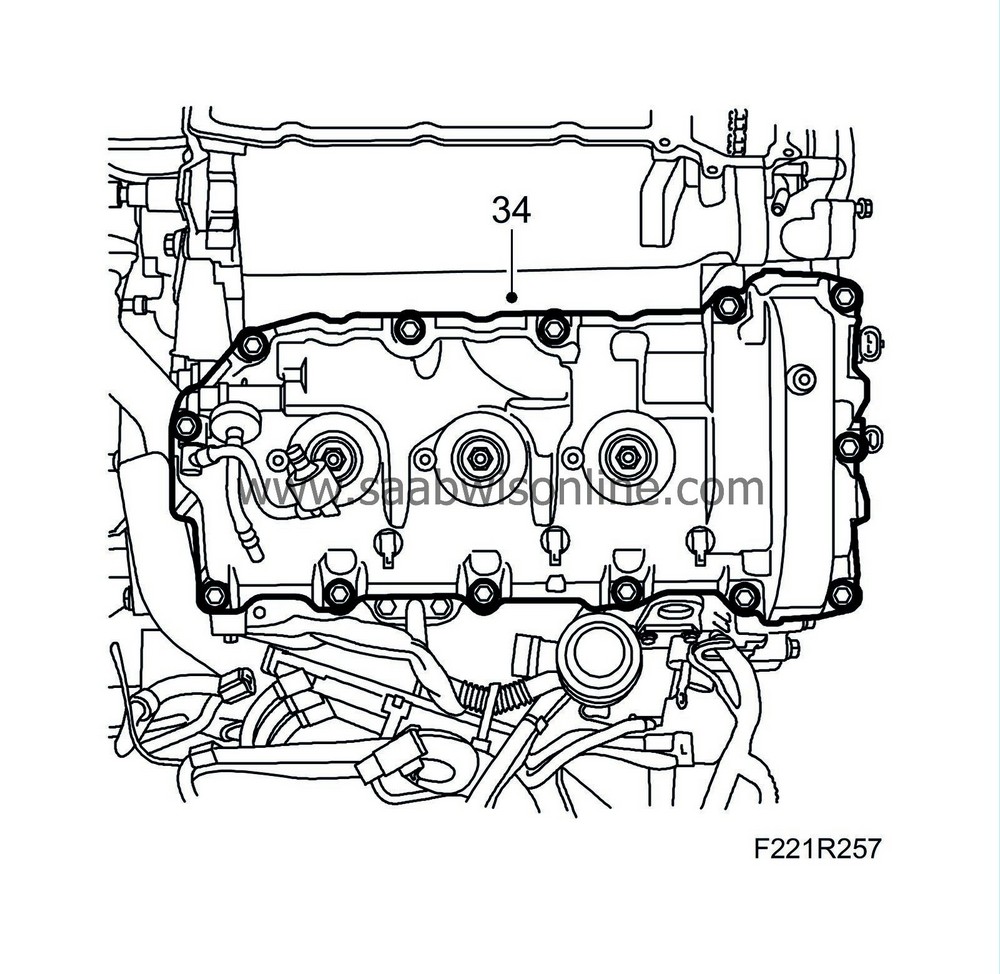
Remove the camshaft cover bolts.
|
|
| 34. |
Raise the wiring harness and servo reservoir. Remove the camshaft cover.
|
|
| 35. |
Remove the camshaft cover gasket and seals around the spark plug holes.

|
|
| To fit |
| 1. |
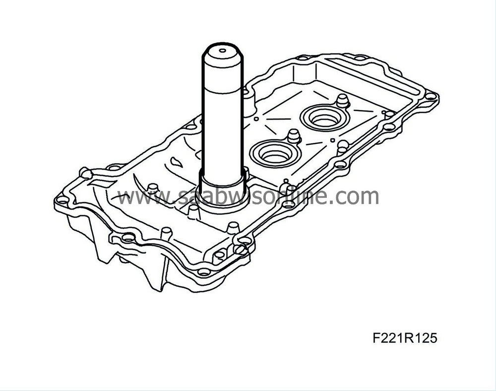
Fit new seals on the camshaft cover. Use
J-5590 Drift
and
J-24254-A Fitting tool
.
|
|
| 2. |
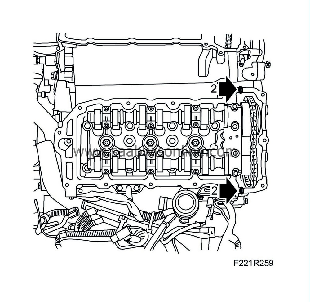
Add a spot of
93 160 951 Flange sealant
to each mating surface between the cylinder head and timing cover as illustrated.
|
|
| 3. |
Position the camshaft cover.
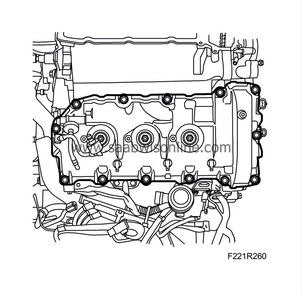
|
|
| 4. |
Fit the bolts using new seals.
Tightening torque 10 Nm (7 lbf ft) |
|
| 5. |
Fit the cable duct on the camshaft cover.
|
|
| 6. |
Fit ignition coils 1, 3 and 5.

|
|
| 7. |
Fit the connectors of the lower oxygen sensor and ignition coils 1, 3 and 5.
|
|
| 8. |
Plug in the 7-pin contact connector.
|
|
| 9. |
Fit the vacuum pipe to the venturi valve.
|
|
| 10. |
Fit the connector and pipe to the fuel bleeder valve.

|
|
| 11. |
Fit the wiring harness to the camshaft cover.
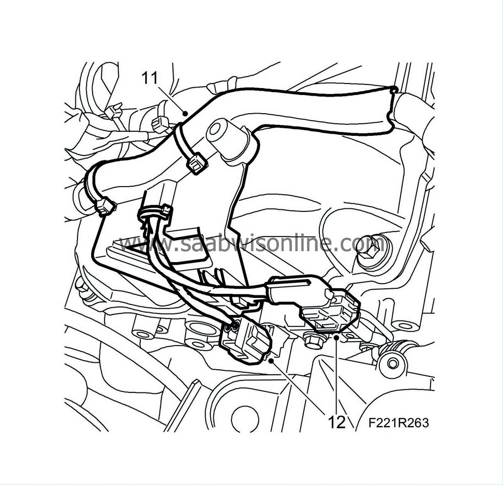
|
|
| 12. |
Plug in the connectors of the camshaft position sensor and the camshaft solenoid valve.
|
|
| 13. |
Clean the sealing surface between the intake manifold and the cylinder head. Fit a new gasket.
|
|
| 14. |
Position the intake manifold and plug in the throttle body connector.

|
|
| 15. |
Fit the intake manifold bolts.
Tightening torque 23 Nm (17 lbf ft) |
|
| 16. |
Fit the fuel line.

|
|
| 17. |
Fit the fuel pressure sensor connector.
|
|
| 18. |
Fit the crankcase ventilation to the intake manifold.
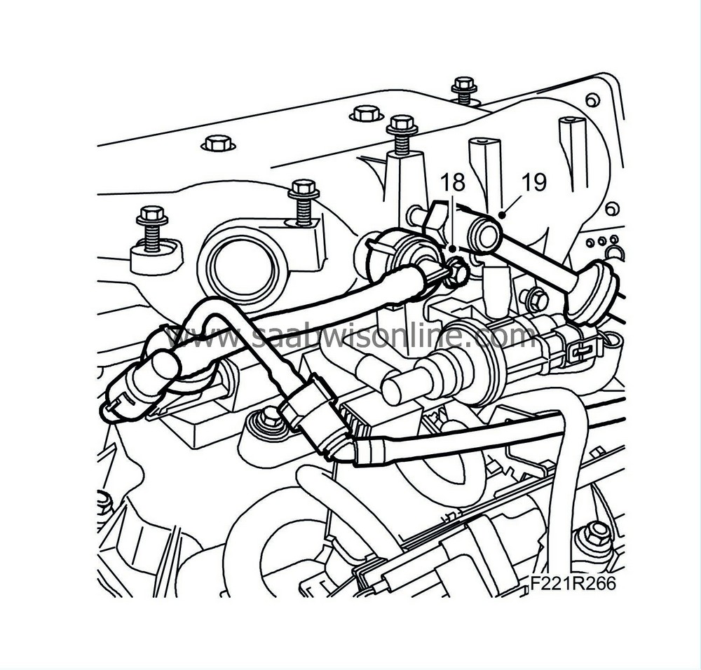
|
|
| 19. |
Fit the brake vacuum hose to the intake manifold.
|
|
| 20. |
Plug in the injector connectors and fit the bracket.

|
|
| 21. |
Reposition the corner bracket and fit the bolts.
|
|
| 22. |
Plug in the atmospheric pressure sensor connector.
|
|
| 23. |
Fit the cable duct to the intake manifold.
|
|
| 24. |
Plug in the engine control module connectors (608A and 608B).

|
|
| 25. |
Fit the ground cable of the engine control module.
|
|
| 26. |
Plug in the connectors of the camshaft position sensor and the camshaft solenoid valve.

|
|
| 27. |
Fit the wiring harness to the camshaft cover using new cable ties.
|
|
| 28. |
Secure the ground cable to the wiring harness.
|
|
| 29. |
Plug in the coolant temperature sensor connector and press down the heat shield.
|
|
| 30. |
Fit ignition coils 2, 4 and 6. Plug in the connectors.
|
|
| 31. |
Fit the left grounding point.
|
|
| 32. |
Fit the power steering fluid reservoir's bolt.
Tightening torque 10 Nm (7 lbf ft) 
|
|
| 33. |
Fit the secondary air pipe and check that the quick-coupling engages.
|
|
| 34. |
Fit the bleeder pipe.
Tightening torque 10 Nm (7 lbf ft) 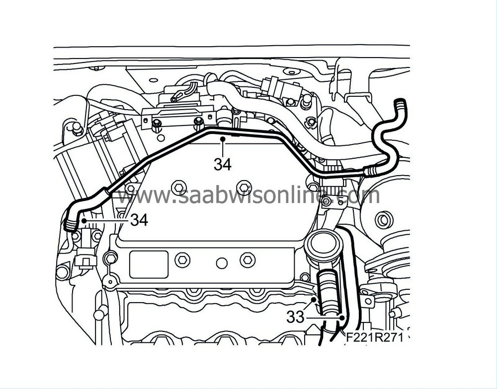
|
|
| 35. |
Fit
Heat shield between engine and turbo
.
|
|


 Warning

