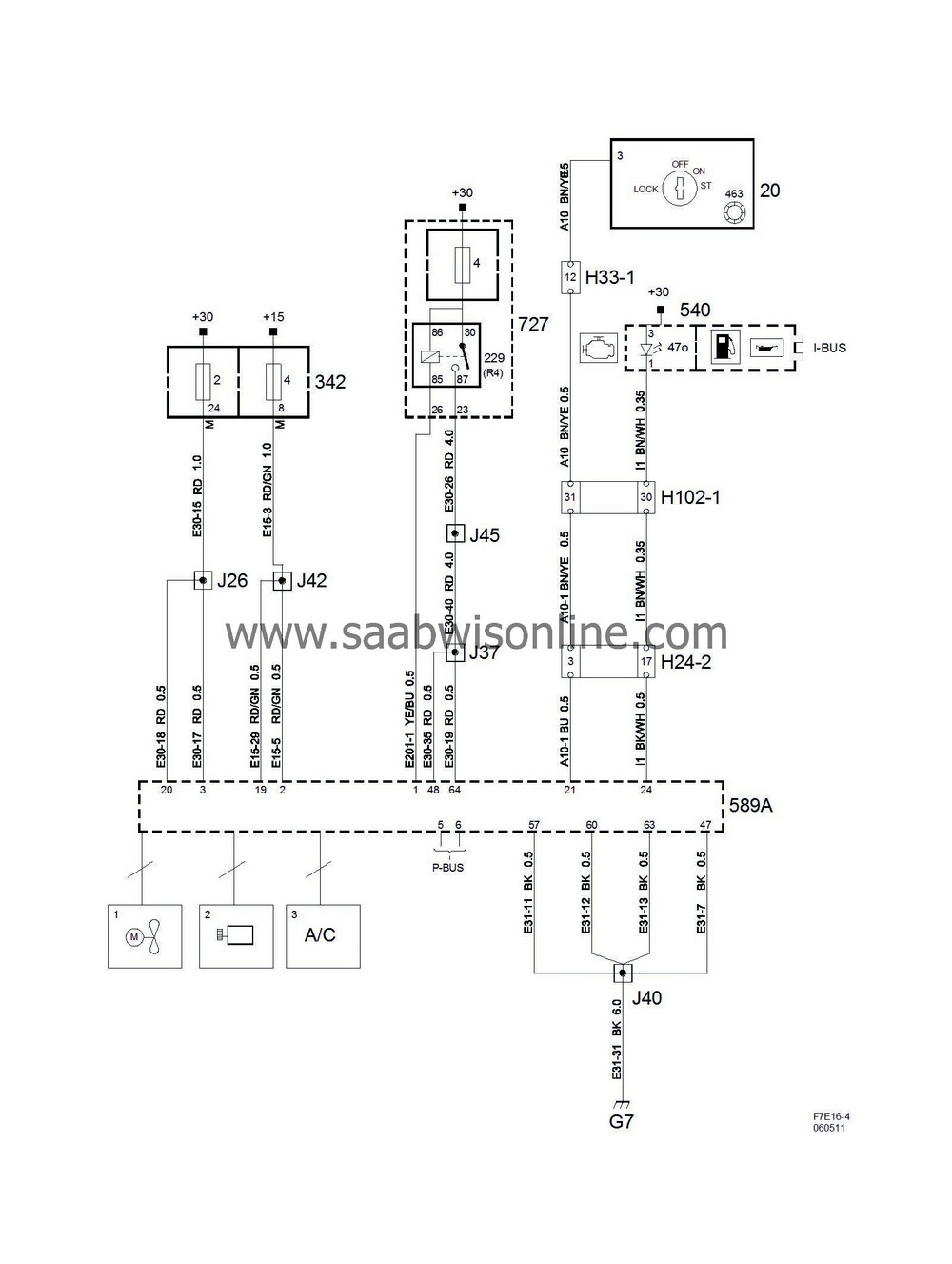
Engine management system Trionic T8 (Part 4/4)
|
|
Engine management system Trionic T8 (Part 4/4)
|
T8 also controls the following systems:
|
No.
|
Name
Location
|
Illus.
|
|
|
Components
|
|
|
20
|
Ignition switch module,
in the floor console between the front seats
|

|
|
229
|
Main relay, engine control system
in the main fuse box in front of battery
|

|
|
342
|
Electrical centre, engine bay
next to battery
|
2
4
|
|
463
|
Antenna unit, immobilizer,
in the ignition switch module
|
|
|
540
|
Main instrument unit,
in front of driver in the dashboard
|

|
|
589A
|
Trionic engine control module, 4-cyl petrol, switch A
on front of engine
|

|
|
727
|
Electrical centre, petrol engine
in front of battery
|
4
|
|
|
24-pin connector
|
|
|
H24-2
|
Grey connector in front of the battery of the side of the left structure strut
|

|
|
|
33-pin connector
|
|
|
H33-1
|
Black connector on the console to the left of the ignition switch
|

|
|
|
102-pin connector
|
|
|
H102-1
|
Under left A-pillar
|

|
|
|
Crimp connections
|
|
|
J26
|
Approx. 170 mm from branching point connector H24-2 towards the engine control module
|

|
|
J37
|
Approx. 260 mm from branching of crankshaft sensor towards the engine control module
|

|
|
J40
|
Approx. 190 mm from branching point crankshaft sensor towards the engine control module
|

|
|
J42
|
Approx. 20 mm from branching point crankshaft sensor towards the engine oil pressure switch
|

|
|
J45
|
Approx. 250 mm from branching point connector H24-2 towards the engine control module
|

|
|
|
Grounding points
|
|
|
G7
|
on the engine control module's top right attachment lug
|

|


