Turbocharger, 4WD
| Turbocharger, 4WD |
| To remove |
|
|||||||
|
|||||||||||||
| 1. |
Remove the battery cover and the engine cover.
|
|
| 2. |
Take the cap (A) off the expansion tank to release any pressure.

|
|
| 3. |
Remove the battery cable.
|
|
| 4. |
Raise the car.
|
|
| 5. |
Undo the right-hand side of the spoiler shield.
|
|
| 6. |
Place a suitable receptacle under the radiator. Connect a hose (A) to the radiator (B) and drain the coolant. Close the cock and refit the spoiler shield.

|
|
| 7. |
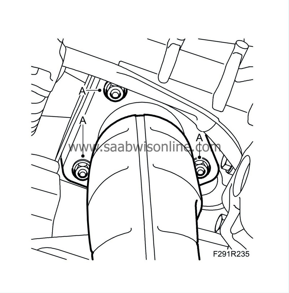
Remove the front nuts (A) of the rear catalytic converter and move aside. Fix in position with
83 95 212 Strap
.
|
|
| 8. |
RHD:
Remove
Alternator, B284, 4WD, (RHD)
.
|
|
| 9. |
LHD:
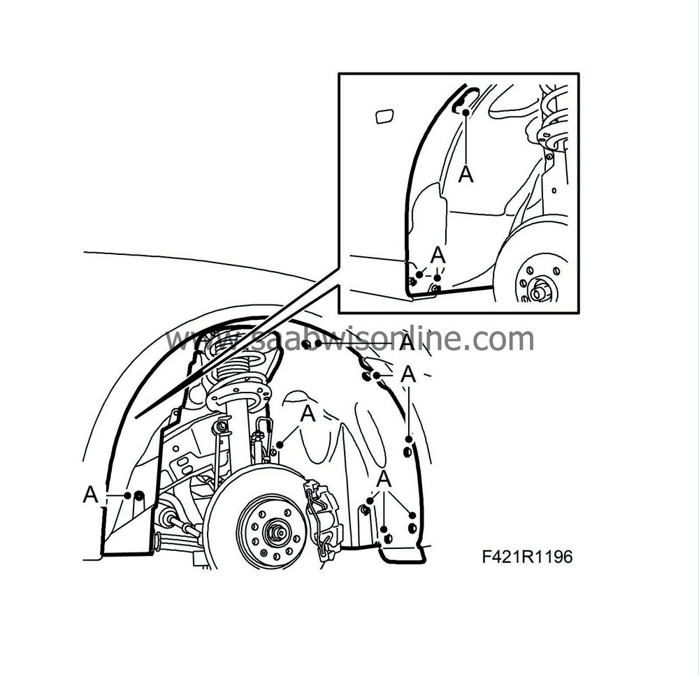
Remove the right wing liner (A).
|
|
| 10. |
LHD:
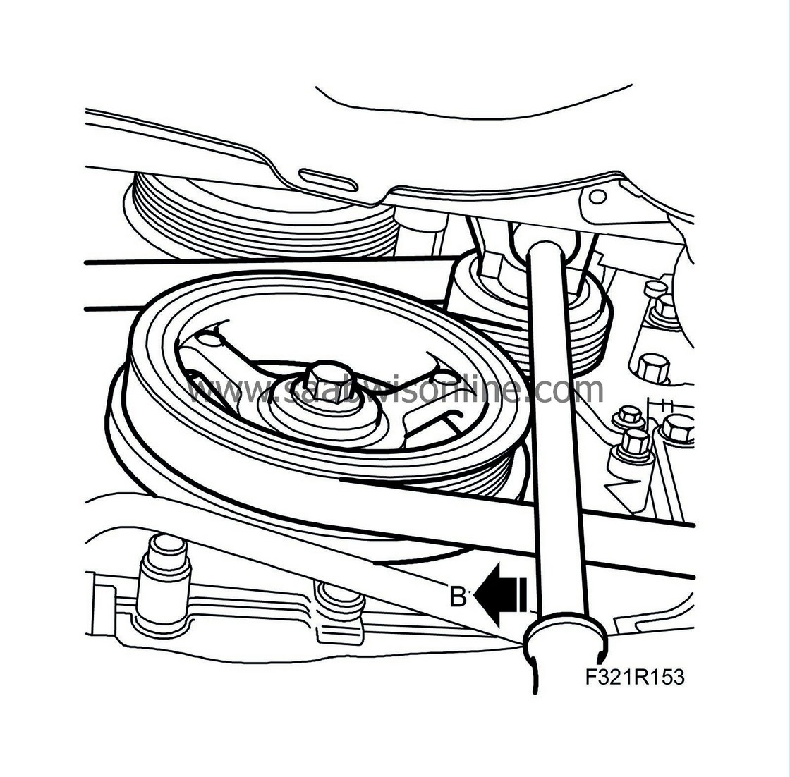
Relieve the load on the belt tensioner and unhook the belt. Use a ½" puller (B).
|
|
| 11. |
LHD:
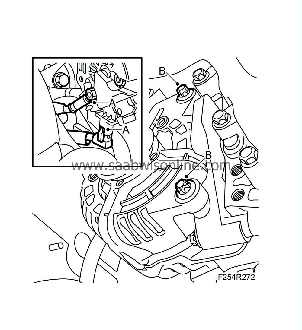
Disconnect the electrical connections (A) of the alternator.
|
|
| 12. |
LHD:
Remove the alternator retaining bolts (B). Move the engine to the left slightly if necessary. Move the alternator rearward.
|
|
| 13. |
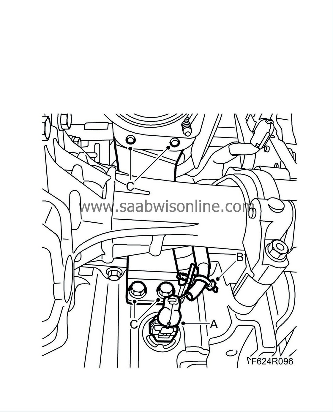
Unplug the oil level sensor connector (A) and remove the cable fixing (B).
|
|
| 14. |
Remove the bracket (C) from the front catalytic converter and oil sump.
|
|
| 15. |
Lower the car.
|
|
| 16. |
Remove the
Fan cowling
.
|
|
| 17. |
Detach the hoses (A) from the expansion tank.

|
|
| 18. |
Move up the tank, unplug the level sensor connector (B) and remove the quick coupling of the coolant hose (C). Lift away the coolant reservoir.
|
|
| 19. |
Remove the upper heat shield from the turbocharger (A) and catalytic converter (B).

|
|
| 20. |
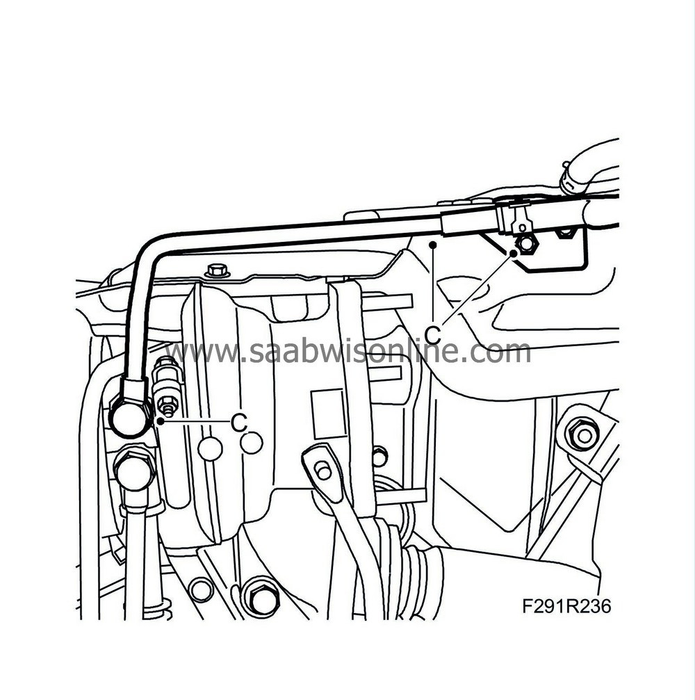
Remove the turbocharger coolant return pipe (C).
|
|
| 21. |
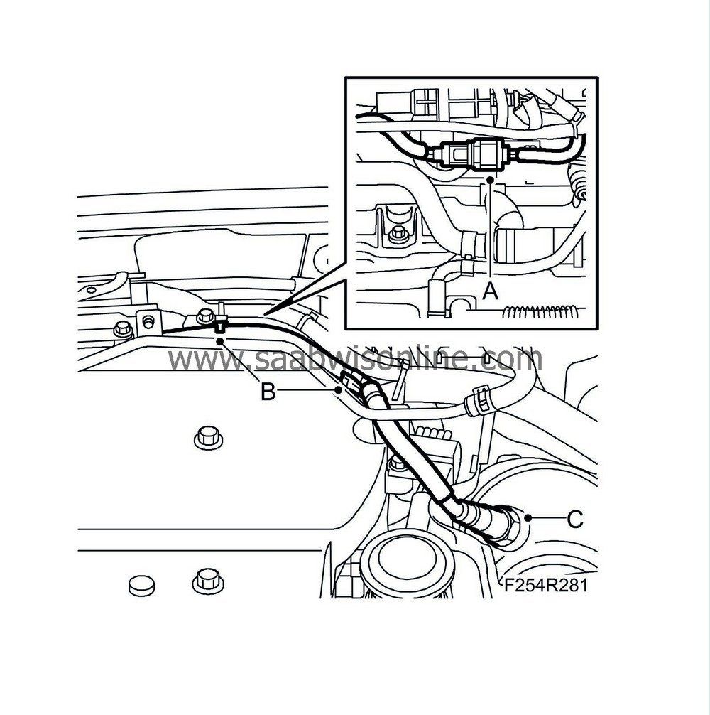
Unplug the connector of the upper oxygen sensor (A) and move up the cable (B).
|
|
| 22. |
Carefully raise the heat shield slightly. Use
83 96 350 Removal socket, oxygen sensor
when removing the oxygen sensor (C).
|
|
| 23. |
Remove the nuts (A). Lubricate the studs and nuts with rust removal oil.

|
|
| 24. |
Remove the catalytic converter from the bracket (B) and move it aside.
|
|||||||
| 25. |
Detach the inlet pipe (A) of the secondary air injection pump from the pump.

|
|
| 26. |
Detach the outlet pipe (B) of the secondary air injection pump from the pump.
|
|
| 27. |
Unplug the connector (C) of the secondary air pressure sensor (760).
|
|
| 28. |
Remove the pipe (D).
|
|
| 29. |
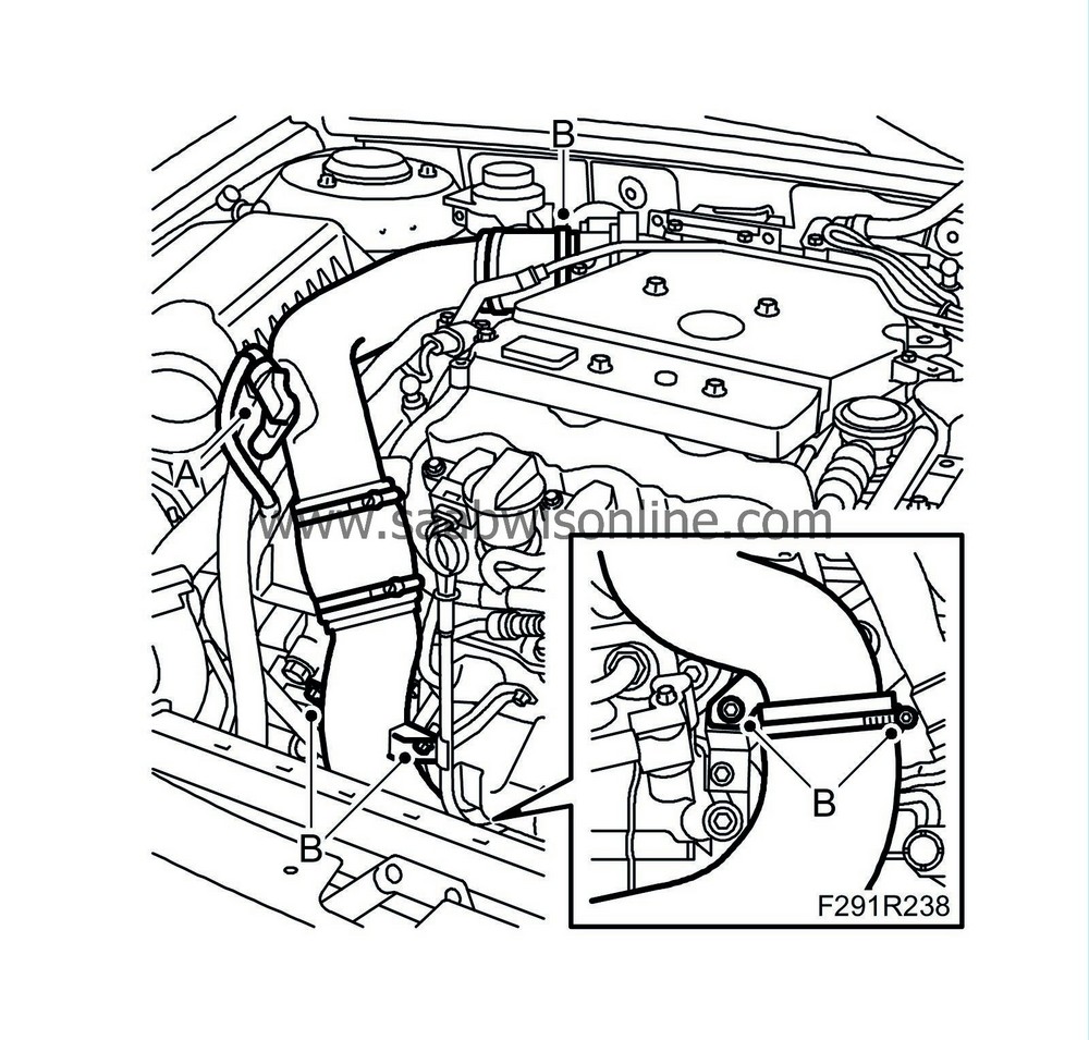
Unplug the intake air sensor connector (688) (A).
|
|
| 30. |
Detach the upper turbocharger delivery pipe (B).
|
|
| 31. |
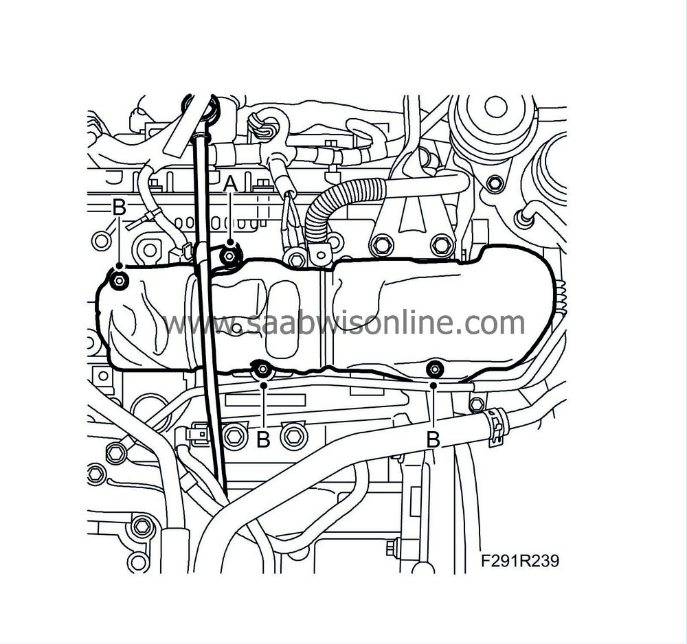
Remove the screw (A) holding the dipstick tube.
|
|
| 32. |
Remove the heat shield (B) of the front exhaust manifold.
|
|||||||
| 33. |
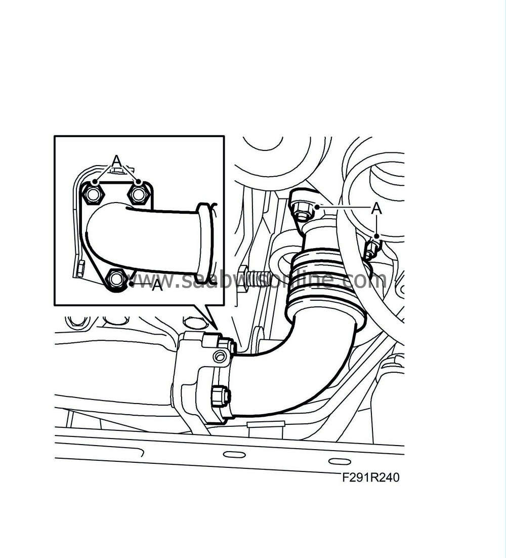
Detach the intermediate exhaust pipe (A) from the turbocharger and the front exhaust manifold.
|
|
| 34. |
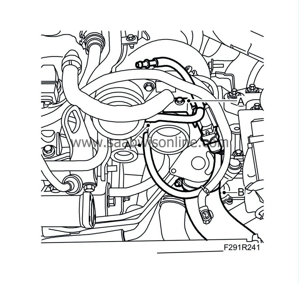
Detach the vacuum hoses and crankcase ventilation pipe from the turbocharger (A).
|
|
| 35. |
Detach the lower turbocharger delivery hose (B) from the turbocharger.
|
|
| 36. |
Detach the oil delivery pipe (A) from the engine.

|
|
| 37. |
Remove the oil return pipe (A) from the turbocharger.

|
|
| 38. |
Remove the oil delivery pipe's banjo screws (B) from the turbocharger.
|
|
| 39. |
Remove the coolant pipe's banjo screw (C) from the turbocharger.
|
|
| 40. |
Remove the nuts (D) of the rear intermediate exhaust pipe.
|
|
| 41. |
Remove the bolt (E) securing the turbocharger to the bracket using an impact socket and long puller. Remove the turbocharger.
|
|
| To fit |
| Important | ||
|
It is essential that there is oil in the turbocharger bearing housing when the engine is started, especially after a new turbocharger has been fitted. |
||
|
Fill the turbocharger's oil inlet with oil from an oilcan. Rotate the compressor wheel by hand a number times to ensure that oil enters the bearings. |
||
| 1. |
Position the turbocharger.
|
|
| 2. |
Fit the bolt (E) securing the turbocharger to the bracket.
Tightening torque: 65 Nm (48 lbf ft)
|
||||||||||
| 3. |
Fit the nuts (D) of the rear intermediate exhaust pipe. Tighten alternatingly.
Tightening torque 30 Nm (22 lbf ft) |
|
| 4. |
Fit the coolant pipe's banjo screw (C) to the turbocharger. Use new gaskets.
Tightening torque 30 Nm (22 lbf ft) |
|||||||
| 5. |
Fit the oil delivery pipe's banjo screws (B) to the turbocharger using new gaskets.
Tightening torque 30 Nm (22 lbf ft) |
|||||||
| 6. |
Fit the oil return pipe (A) to the turbocharger. Use new gaskets.
Tightening torque: 14 Nm (10 lbf ft) |
|
| 8. |
Attach the lower turbocharger delivery hose (B) to the turbocharger.

|
|
| 9. |
Attach the vacuum hoses and crankcase ventilation pipes to the turbocharger (A).
|
|
| 10. |
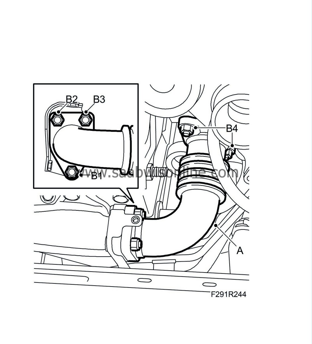
Attach the intermediate exhaust pipe (A) to the front exhaust manifold and the turbocharger. Use a new gasket and coat the studs with
90 513 210 Universal paste
.
|
||||||||||
| 11. |
Tighten the nuts as illustrated - first on the exhaust manifold and then on the turbocharger.
Tightening order (B1, B2, B3 and B4) alternatingly on the turbocharger. Tightening torque 30 Nm (22 lbf ft)
|
||||||||||
| 12. |
Fit the front exhaust manifold heat shield (B).
Tightening torque 10 Nm (7 lbf ft) 
|
|
| 13. |
Fit the screw (A) holding the dipstick tube.
Tightening torque 10 Nm (7 lbf ft) |
|
| 14. |
Fit the upper turbocharger delivery pipe (B).

|
|
| 15. |
Plug in the intake air sensor connector (688) (A).
|
|
| 16. |
Fit the pipe (D).

|
|
| 17. |
Plug in the connector (C) of the secondary air pressure sensor (760).
|
|
| 18. |
Attach the secondary air injection pump's outlet pipe (B) to the pump.
|
|
| 19. |
Attach the secondary air injection pump's inlet pipe (A) to the pump.
|
||||||||||
| 20. |
Fit the catalytic converter nuts (A) to the turbocharger. Coat the studs with
90 513 210 Universal paste
.
Tightening torque 25 Nm (18 lbf ft) 
|
|
| 21. |
Fit the catalytic converter to the bracket (B).
|
|
| 22. |
Fit the turbocharger's lower heat shield.
|
|
| 23. |
Lightly coat the threads of the front oxygen sensor with
90 513 210 Universal paste
and fit the oxygen sensor (C) using
83 96 350 Removal socket, oxygen sensor
.
Tightening torque 45 Nm (33 lbf ft). 
|
|
| 24. |
Carefully press down the heat shield.
|
|
| 25. |
Secure the cable (B) and plug in the connector (A).
|
|
| 26. |
Fit the turbocharger coolant pipe (C).

Tightening torque, banjo screw: 30 Nm (22 lbf ft).
|
|||||||
| 27. |
Fit the upper heat shield to the catalytic converter (B) and turbocharger (A).

|
|
| 28. |
Attach the lower hose (C) of the coolant reservoir and plug in the level sensor connector (B).

|
|
| 29. |
Fit the coolant reservoir in the mounting.
|
|
| 30. |
Attach the breather hoses (A) to the coolant reservoir.
|
|
| 31. |
Fit
Fan cowling
.
|
|
| 32. |
Raise the car.
|
|
| 33. |
Fit the bracket (C) to the front catalytic converter and oil sump.

|
|
| 34. |
Plug in the oil level sensor connector (A) and attach the cable fixing (B).
|
|
| 35. |
RHD:
Remove
Alternator, B284, 4WD, (RHD)
.
|
|
| 36. |
LHD:
Fit the alternator retaining bolts (B).

|
|
| 37. |
LHD:
Connect the electrical connections (A) of the alternator.
|
|
| 38. |
LHD:
Relieve the load on the belt tensioner and position the belt. Use a ½" puller (B).

|
|
| 39. |
LHD:
Fit the right wing liner (A).

|
|
| 40. |
Fit the rear catalytic converter (A) using a new gasket.
Tightening torque 25 Nm (18 lbf ft) 
|
|
| 41. |
Lower the car.
|
|
| 42. |
Carry out
Cooling system pressure testing
and
Bleeding and charging the cooling system
.
|
|
| 43. |
Check the oil level and top up as necessary.
|
|
| 44. |
Connect the battery cable.
|
|
| 45. |
Fit the battery cover and the engine cover.
|
|
| 46. |
Remove the wing covers and restore car electrical functions, see
After disconnecting the battery
.
|
|
| 47. |
Start the engine and check for any exhaust, oil and coolant leakage.
|
|

 Warning

