Subframe, 4WD, A20NFT/LHU
| Subframe, 4WD, A20NFT/LHU |
| To remove |
| 1. |
Remove the upper bumper shell attachments.
|
|
| 2. |
Hang two
83 95 212 Straps
in place over the radiator member and the radiator unit so that they are accessible from below.
|
|
| 3. |
Raise the car.
|
|
| 4. |
Remove the front wheels.
|
|
| 5. |
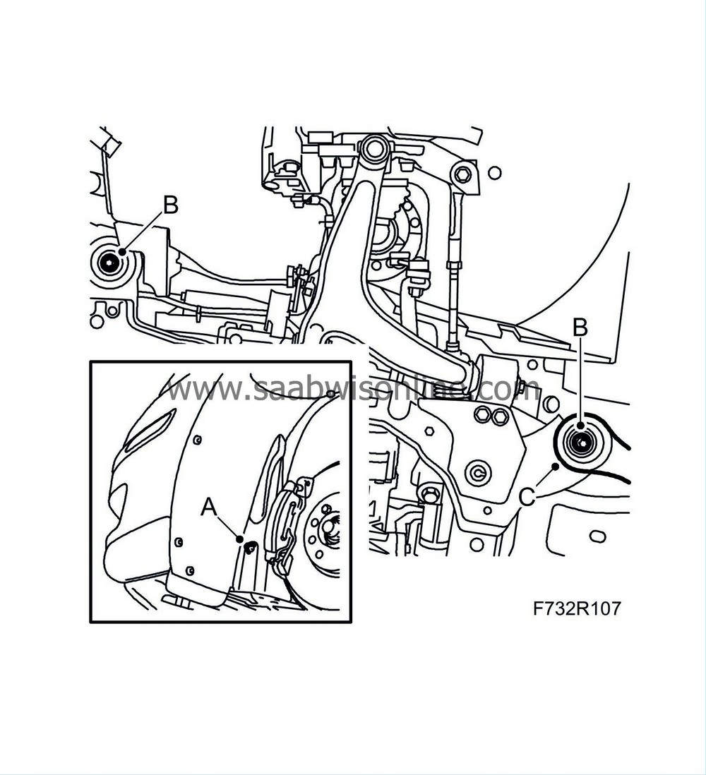
Remove the lower front cover (A).

|
|
| 6. |
Bind the radiator unit tightly with the straps.
|
|
| 7. |
Remove the radiator brackets (B) from the subframe.
|
|
| 8. |
Remove
propeller shaft
.
|
|
| 9. |
Remove the engine's front torque rod (A) from the subframe.

|
|
| 10. |
Remove the bolt and nut (B) holding the suspension arm to the steering swivel member on both sides.

|
|
| 11. |
Cars with Xenon lights:
Remove the level sensor (C) on the left-hand suspension arm, and the wiring harness' clip.
|
|
| 12. |
Remove the steering gear from the subframe (A). Keep the nuts and washers safe. Leave the steering gear hanging.

|
|
| 13. |
Open the clamps (A) that secure the power steering pipe to the subframe.

|
|
| 14. |
Position
83 95 311 Trolley lift
with
83 94 801 Parent fixture
and
83 96 137 Centring tool, subframe - body

|
|
| 15. |
Remove the front part of the wing liner (A) and bend it out of the way.

|
|
| 16. |
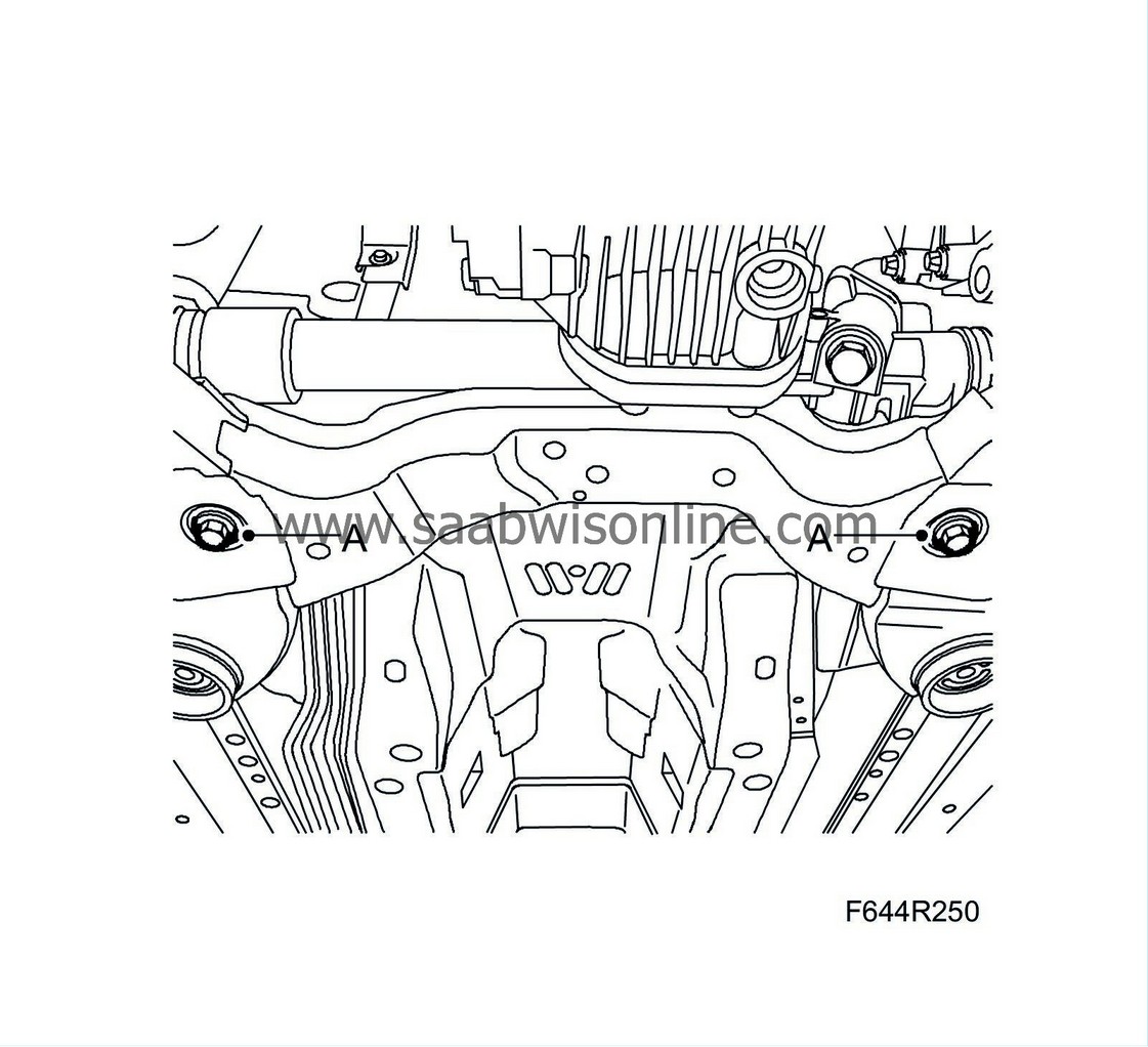
Remove the subframe bolts (B) on both sides. Detach the stays (C) from the body.
|
|
| 17. |
Remove the bolts (D) holding the rear torque rod to the subframe.

|
|
| 18. |
Lower the subframe slightly.
|
|
| 19. |
Pull out the suspension arms ball-and-socket joints from the steering swivel members.
|
|
| 20. |
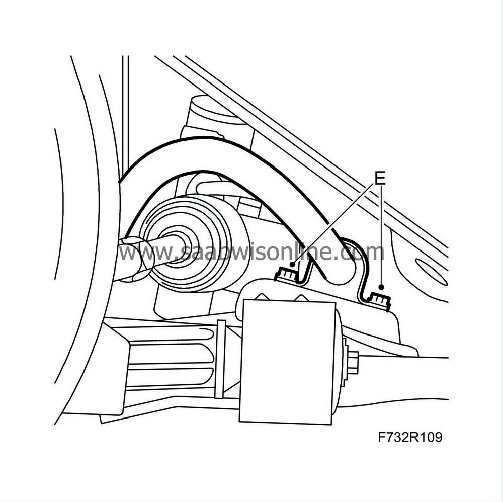
Remove the anti-roll bar (E) from the subframe.

|
|
| 21. |
Lower the subframe.
|
|
| 22. |
Subframe replacement:
Remove the suspension arms and rear torque rod (A).

|
|
| To fit |
| 1. |
Place the frame on the
83 95 311 Trolley lift
with
83 94 801 Parent fixture
and
83 96 137 Centring tool, subframe - body
.
|
|
| 3. |
Lift the frame.
|
|
| 4. |
Fit the anti-roll bar (E) to the subframe. Use
Threadlock, Loctite 242
.
Tightening torque 18 Nm (13 lbf ft). 
|
|
| 5. |
Fit the ball joints for the suspension arms in the steering swivel member.
|
|
| 6. |
Lift the subframe into place and align
83 96 137 Centring tool, subframe - body
with the locating holes in the body.
|
|
| 7. |
Attach the power steering pipe to the plastic clips on the subframe (A).

|
|
| 8. |
Lift the subframe so that the inner sections of the bushes are pressing against the body. Fit the front subframe bolts (B) on both sides.
Tightening torque 75 Nm +135° (55 lbf ft +135°) 
|
|
| 9. |
Fit the stays and the rear subframe bolts (B) on both sides. Insert the rear stay bolts (C) before tightening the subframe bolts.
Tightening torque 75 Nm +135° (55 lbf ft +135°) |
|
| 10. |
Lower and pull away the trolley lift.
|
|
| 11. |
Tighten the rear stays' bolts (C).
Tightening torque 90 Nm +45° (66 lbf ft +45°) |
|
| 12. |
Fit the front part of the wing liners (A).
|
|
| 13. |
Fit the bolts (D) holding the rear torque rod to the subframe.
Tightening torque M10 65 Nm (48 lbf ft) M12 120 Nm (88 lbf ft) 
|
|
| 14. |
Fit the steering gear (A) with bolts, washers and nuts.
Tightening torque 50 Nm +60° (37 lbf ft +60°) 
|
|
| 16. |
Fit the bolt and nut (B) holding the suspension arm to the steering swivel member on both sides.
Tightening torque 50 Nm (37 lbf ft) |
|
| 17. |
Fit the engine's front torque rod (A) to the subframe.
Tightening torque 60 Nm +90° (44 lbf ft +90°) 
|
|
| 18. |
Set up KM6313 Centring tool kit, subframe - engine with
KM-6313-300 Support
and check that the engine is located correctly in relation to the subframe. Remove the centring tool.
|
|
| 19. |
Fit the
propeller shaft
.
|
|
| 20. |
Fit the radiator brackets (B) to the subframe.
Tightening torque 47 Nm (35 lbf ft)

|
|||||||
| 21. |
Remove the straps.
|
|
| 22. |
Fit the lower front cover (A).
|
|
| 23. |
Fit the
Wheels.
|
|
| 24. |
Lower the car to the floor.
|
|
| 25. |
Fit the upper bumper shell attachments.
|
|
| 26. |
Check the straight-ahead position of the steering wheel when driving on a level road. Adjust if necessary.
|
|
| 27. |
Replacement of subframe:
Carry out
Four wheel alignment
.
|
|

 Warning

