Rear Wheel Drive Shaft Inner Joint and Boot Replacement
|
|
Rear Wheel Drive Shaft Inner Joint and Boot Replacement
|
Special Tools
DT 35910
Drive Axle Seal Clamp Pliers
For equivalent regional tools, refer to
Special Tools
.
|
Note
|
|
The tripot assembly and the internal parts for the tripot assembly are not serviceable. If the tripot assembly is found to have excessive wear or damage, replace the wheel drive shaft as an assembly.
|
|
2.
|
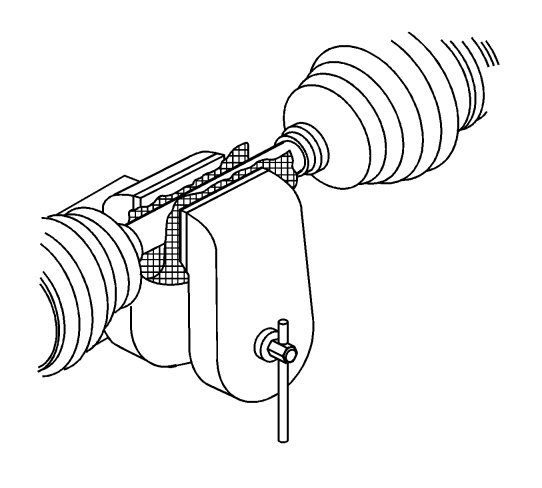
Position the wheel drive shaft in a soft jawed vise and clamp securely.
|
|
3.
|
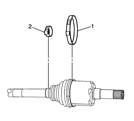
Using a flat-bladed tool, remove the boot retaining clamp (2).
|
|
4.
|
Using side cutters, remove the boot clamp (1).
|
|
5.
|
|
Note
|
|
The tripot housing may be staked at the end to prevent removal. The staking will need to be ground down to allow removal.
|
Remove the tripot housing (1) from the wheel drive shaft.

|
|
6.
|
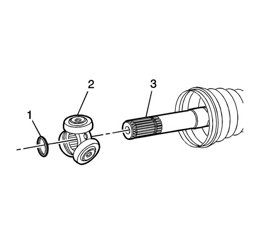
Remove the retaining clip (1) and the tripot spider (2) from the wheel drive shaft (3).
|
|
7.
|
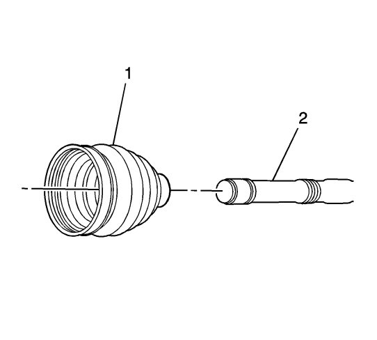
Remove the boot (1) from the wheel drive shaft (2).
|
|
1.
|
|
Note
|
|
Ensure the boot clamp is positioned correctly in the seal groove.
|
Position the boot (1) on the wheel drive shaft (2).

|
|
2.
|
Install the tripot spider assembly (2) to the wheel drive shaft (3), until seated against the shoulder.

|
|
3.
|
Install the retaining ring (1) in the wheel drive shaft (3).
|
|
4.
|
Place approximately half of the grease in the kit into the boot and place the remainder in the tripot housing.
|
|
5.
|
Install the tripot housing (1) on the wheel drive shaft.

|
|
6.
|
Install the inboard boot clamp (2).

|
|
7.
|
Install the outboard boot clamp (1).
|
|
8.
|
Using the
DT 35910
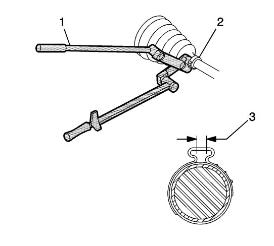
pliers , breaker bar, torque wrench and or ratchet (1) , close the boot clamp (2) until the gap (3) measures
2.15 mm (0.085 in)
.
|
|
9.
|
Using the
DT 35910
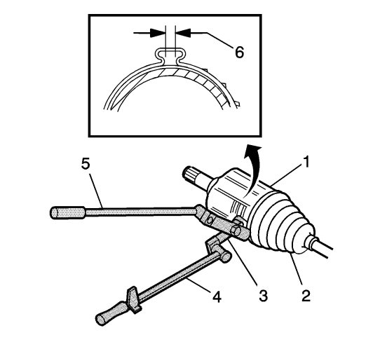
pliers (3), breaker bar (5), torque wrench and or ratchet (4), close the clamp until the gap (6) measures
1.9 mm (0.070 in)
.
|
|
10.
|
Rotate the housing in a circular motion to distribute the grease in the tripot joint.
|


