Front Wheel Drive Shaft Replacement
| Front Wheel Drive Shaft Replacement |
Special Tools
| • |
DT-44394-A
Seal Protector
|
|
| • |
J-45859
Axle Puller
|
|
For equivalent regional tools, refer to Special Tools .
| Removal Procedure |
| 1. |
Raise and support the vehicle. Refer to
Lifting and Jacking the Vehicle
.
|
|
| 2. |
Remove the tire and wheel assembly. Refer to
Tire and Wheel Removal and Installation
.
|
|
| 3. |
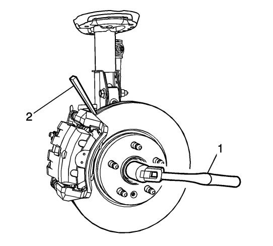
Insert a drift or punch (2) in the cooling fins of the brake rotor.
|
|
| 4. |
Rotate the brake rotor until the drift or punch contacts the brake caliper mounting bracket.
|
|
| 5. |
Using a breaker bar (1), loosen the wheel drive shaft nut.
|
|
| 6. |
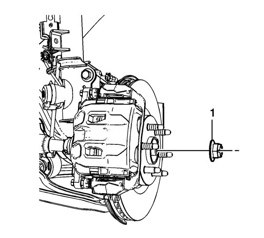
Remove the wheel drive shaft nut (1).
|
|
| 7. |
Using the
J-45859
puller , separate the wheel drive shaft from the knuckle assembly.
|
|
| 8. |
Remove the lower control arm from the knuckle. Refer to
Lower Control Arm Replacement
.
|
|
| 9. |
Remove the outer tie rod end from the knuckle. Refer to
Steering Linkage Outer Tie Rod Replacement
.
|
|
| 10. |
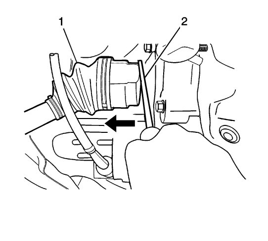
Using a large flat bladed screw driver (2), remove the wheel drive shaft (1) from the differential.
|
|
| 12. |
Remove and discard the washer (1) from the wheel axle (2). DO NOT re-use the gasket, always replace with NEW. 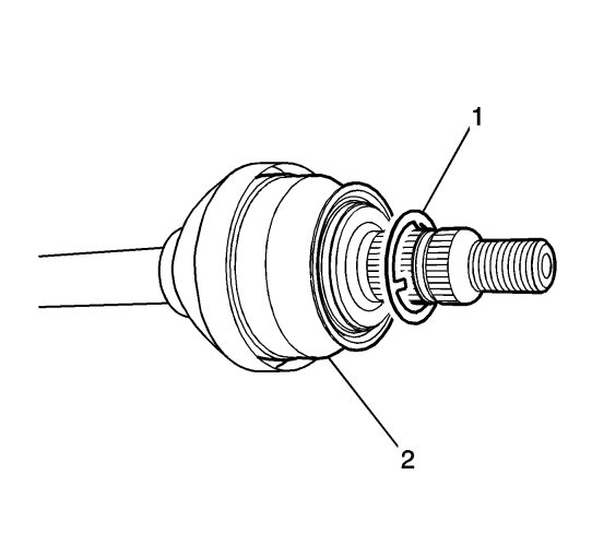
|
|||||||
| 13. |
Remove the front axle shaft seal. Refer to
Front Wheel Drive Shaft Seal Replacement - Left Side
.
|
|
| Installation Procedure |
| 1. |
Install the NEW front axle shaft seal. Refer to
Front Wheel Drive Shaft Seal Replacement - Left Side
.
|
|
| 2. |
Install the DT-44394-A protector (1) into the differential seal. 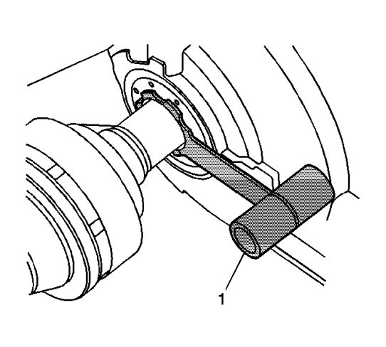
|
|||||||||
| 3. |
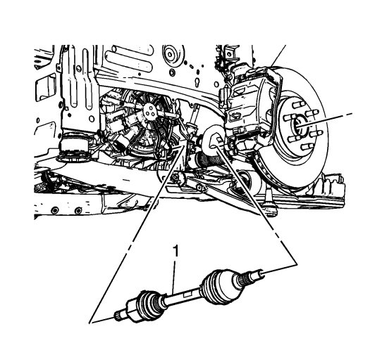
Install the wheel drive shaft (1) into the differential.
|
|
| 4. |
Remove the
DT-44394-A
protector from the wheel drive shaft.
|
|
| 5. |
Install the NEW washer (1) on the wheel drive shaft (2).

|
|
| 6. |
Insert the wheel drive shaft in the knuckle.
|
|
| 7. |
Install the lower control arm in the knuckle. Refer to
Lower Control Arm Replacement
.
|
|
| 8. |
Install the outer tie rod end in the knuckle. Refer to
Steering Linkage Outer Tie Rod Replacement
.
|
|
| 9. |
Install the wheel drive shaft nut (1).

|
|
| 10. |
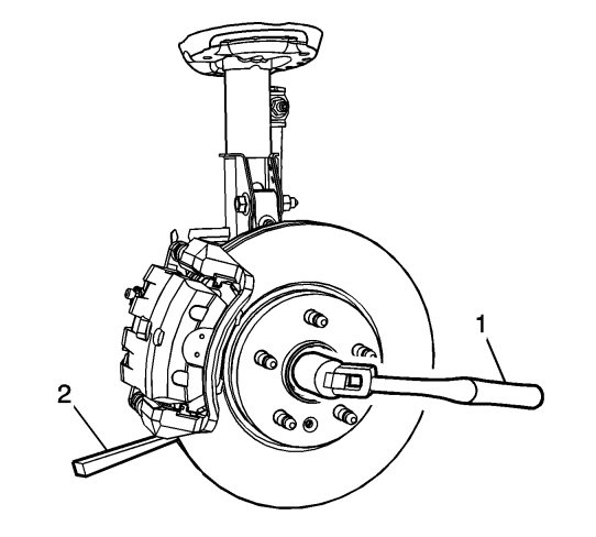
Insert a drift or punch (2) in the cooling fins of the brake rotor.
|
|
| 11. |
Rotate the brake rotor until the drift or punch contacts the brake caliper mounting bracket.
|
|
| 12. |
Refer to
Fastener Caution
.
Use a torque wrench (1) and tighten the drive axle nut to 250 Nm (184 lb ft) . |
|
| 13. |
Install the tire and wheel assembly. Refer to
Tire and Wheel Removal and Installation
.
|
|
| 14. |
Remove the support and lower the vehicle.
|
|

 Warning

