B-Pillar, Sectioning - Outer
| B-Pillar, Sectioning - Outer |
| To remove |
| 1. |
Refer to
Approved Equipment for Collision Repair Warning
.
Refer to Warning during the repair of collision damage with repair sheet metal Refer to Fuel/Fuel vapor Warning .
Disable the SIR system. Refer to SIR Disabling and Enabling . |
|||||||
| 2. |
Disconnect the negative battery cable. Refer to
Battery Negative Cable Disconnection and Connection
.
|
|
| 3. |
Remove all related panels and components.
|
|
| 4. |
Remove sealant and anti-corrosion materials from repair area, if necessary and note their placement.
|
|
| 5. |
Repair as much as possible of the damaged area. Refer to
Body dimensions
.
|
|
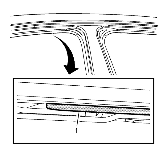
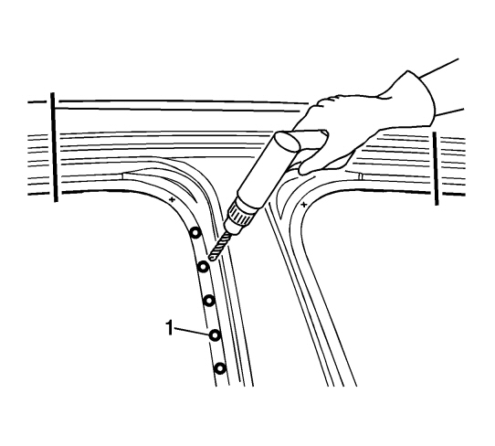
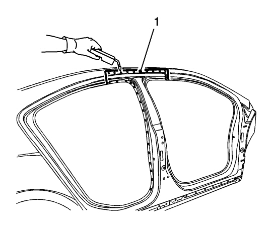
| 6. |
Remove the weatherstrip, note the flange in the center pillar. There will be a 3-metal stack-up. The middle layer is the center pillar's inner reinforcement (1).
|
|
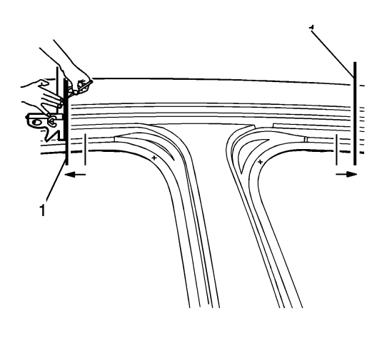
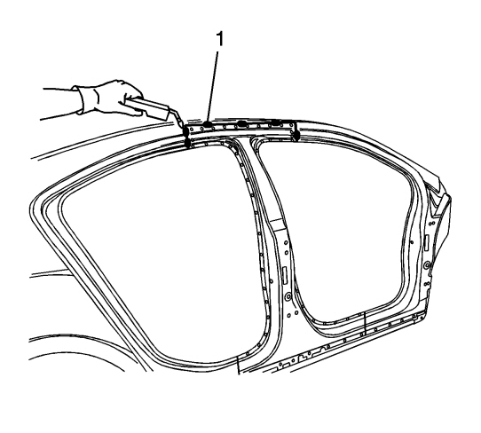
| 7. |
Measure 13 mm (1/2 in) from the front and rear edges of the center pillar's inner reinforcement and mark a vertical line (1).
|
|
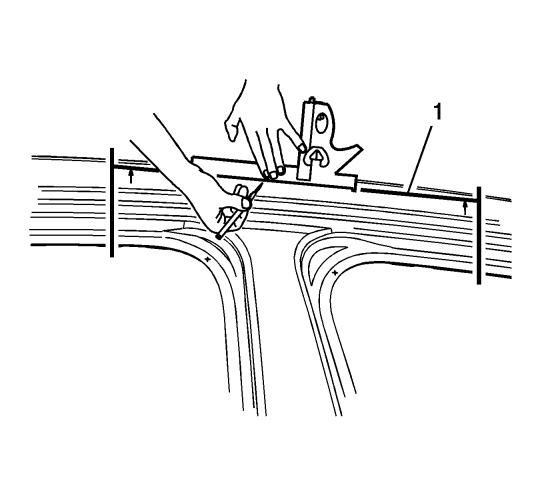
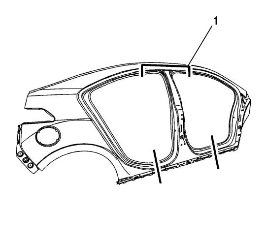
| 8. |
Measure 2.5 cm from the door opening's function line (1) and mark up a horizontal line.
|
|
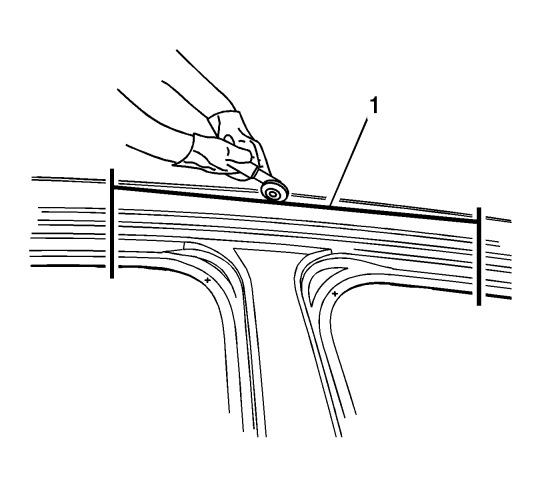
| 9. |
Cut the window (1) in the outer center pillar.
|
|
| 10. |
Perform additional sectioning which may be necessary depending on the damage to the vehicle. Refer to
Quarter Outer Panel Sectioning
,
Rocker Outer Panel Sectioning
, or
Front Hinge Pillar Body Sectioning
.
|
|
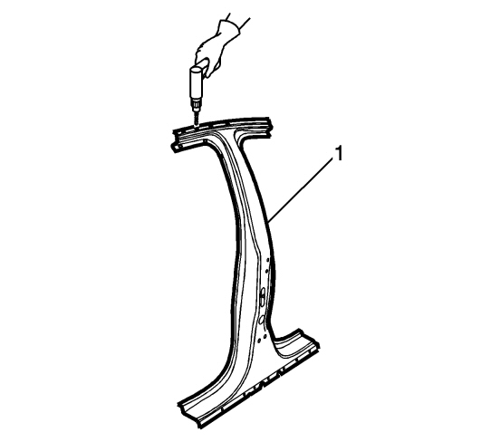
| 11. |
Locate and drill out all factory welds (1). Note the number and location of the welds for installation of the service part.
|
|
| 12. |
Remove the damaged outer center pillar section (1).

|
|
| Installation Procedure |
| 1. |
From the service part, cut the panel at corresponding points in order to overlap the remaining original panel by 25 mm (1 in) at every common point (1).
|
|
| 2. |
Drill 8 mm (5/16 in) plug the weld holes in the service side (1), if necessary, at corresponding points noted on the original panel and along common sections
|
|
| 3. |
If necessary, prepare surfaces for welding.
|
|
| 4. |
Apply GM approved welds through coating or equivalent on all surfaces.
|
|
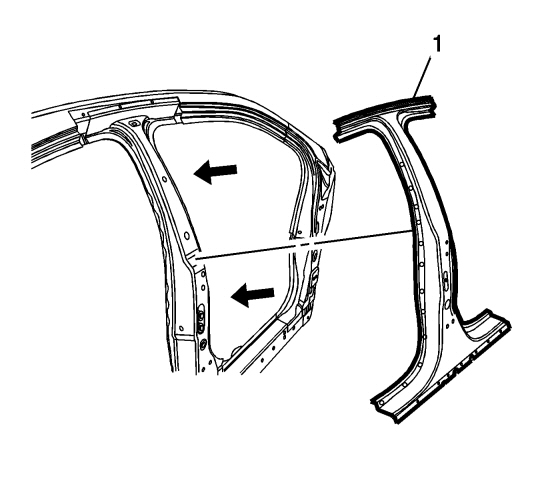
| 5. |
Place the outer center pillar (1) in the vehicle with the 3- dimensional measuring equipment. Secure the pillar in place.
|
|
| 6. |
Plug the welds according to (1) .
|
|
| 7. |
To create a solid weld with minimum heat distortion, make a 25 mm (1 in) Weld bead along 25 mm (1 in) the parts between them. Then go back and complete the weld (1).
|
|
| 8. |
Clean and prepare all welded surfaces.
|
|
| 9. |
Apply sealant and, if necessary, corrosion material to the repair area.
|
|
| 10. |
Paint the repair area. See
Basecoat/Clearcoat Paint Systems
.
|
|
| 11. |
Install all related panels and components.
|
|
| 12. |
Connect the negative battery cable. Refer to
Battery Negative Cable Disconnection and Connection
.
|
|
| 13. |
Activate the SIR system. Refer to
SIR Disabling and Enabling
.
|
|
This project is supported by memberships and donations. If you use this site, please consider Joining SCNA and/or making a donation.
Our Friends
