(210-2131) Valve leak check
|
TECHNICAL SERVICE BULLETIN
|
|
Bulletin Nbr:
|
210-2131
|
|
Date:
...........
|
MAY 1999
|
|
Market:
|
All
|
M1998-99 up to and including VIN X3075350 (4-cyl)
A combination of incorrect clearance between valve and valve guide, low valve spring pressure, bad fuel quality, and counter-pressure from the catalytic converter and turbo, can cause a certain build up of carbon. This may make the exhaust valves stick. Symptoms are vibrations, jerkiness and misfiring under light loads. After customer complaint, change the exhaust valves. Check the valves according to the instructions in this SI.
Exhaust valves, ordered via Saab Automobile, PVP, TAKF.
|
Removal of cylinder head (in situ)
|
|
1.
|
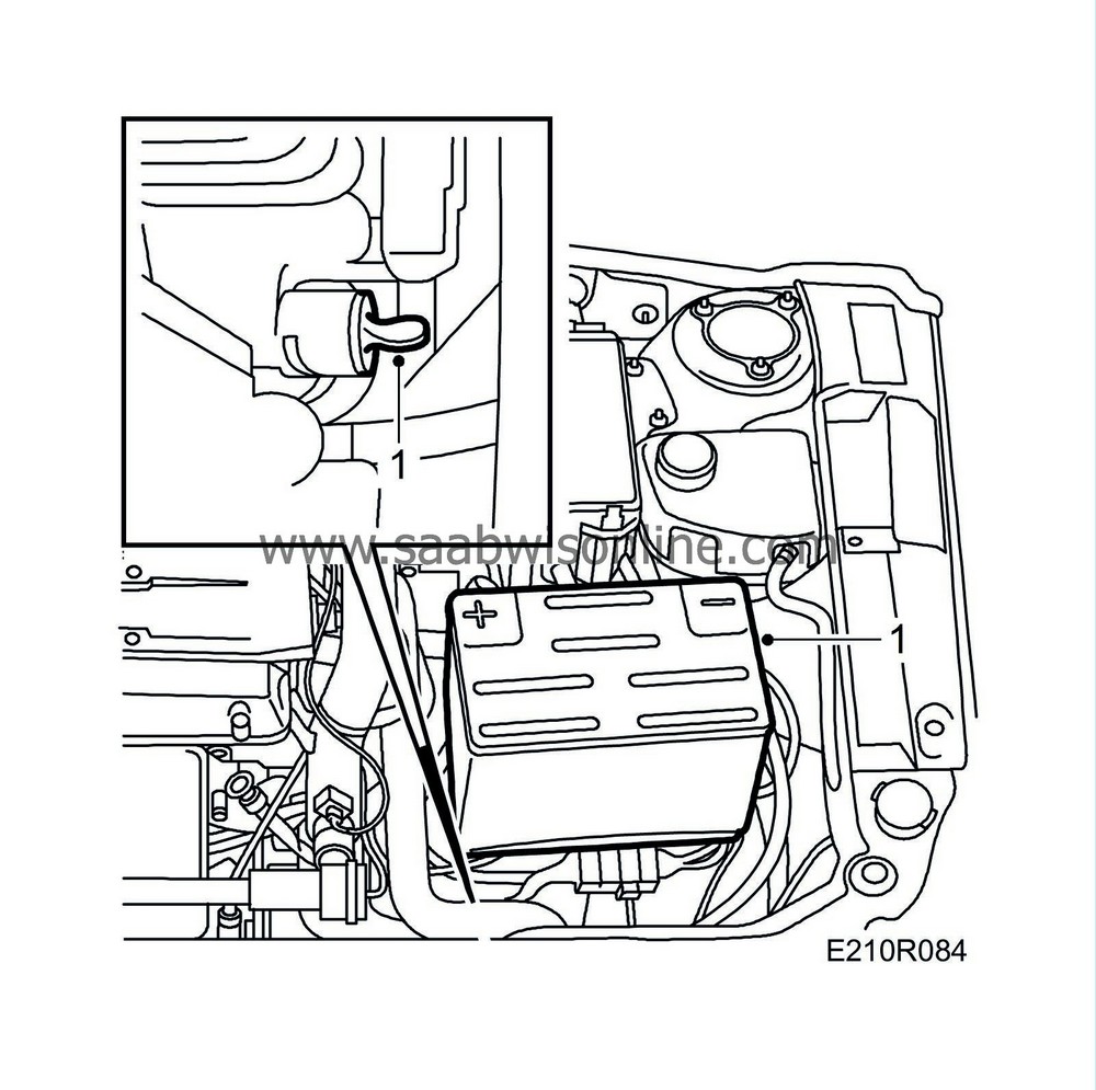
Allow the engine to idle. Remove fuse 19 to avoid residual pressure in the fuel lines while working on the cylinder head. Turn off the ignition when the engine has stopped running. Put back the fuse. Protect the wings and remove the covers from the battery and intake manifold. Drain the engine coolant and disconnect the negative battery cable. Raise the car and remove the bottom engine cover.
|
|
2.
|
Lower the car slightly, remove the front right wheel and detach the steering servo pipe from the subframe.

|
|
3.
|
Drive in a wedge 83 95 238 between the oil sump and subframe on the right-hand side.
|
|
4.
|
Remove the right-hand engine mounting with yoke and the bracket for the servo pump pipe.
|
|
5.
|
Remove the mass air flow sensor with rubber gaiter. Unplug the connectors for the mass air flow sensor and turbo wastegate.
|
|
6.
|
Remove the crankcase breather pipe.
|
|
7.
|
Remove the front lifting eye from the engine and pull it out of the rubber.
|
|
8.
|
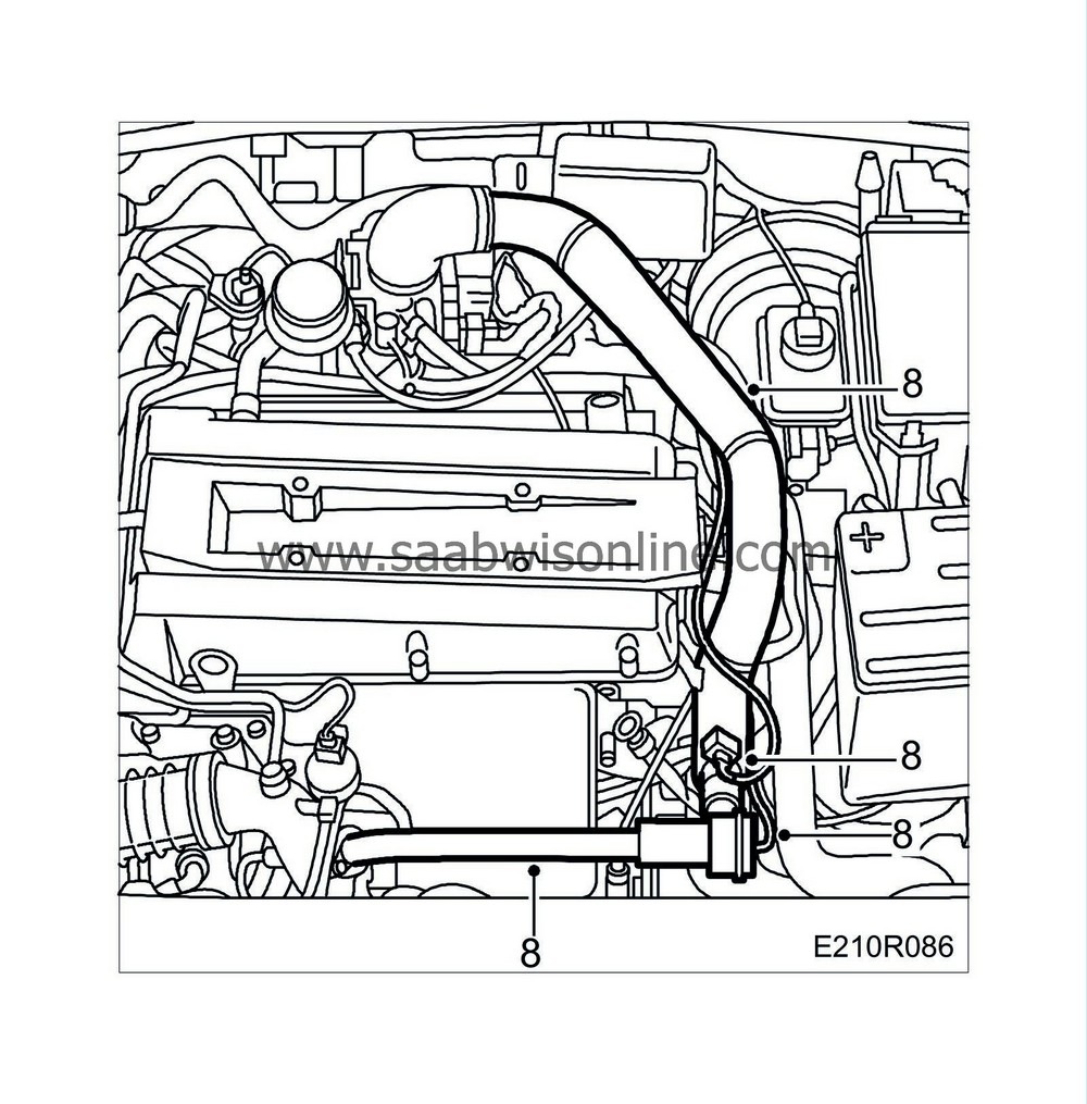
Remove the pressure pipe and bypass valve and disconnect the bypass valve's vacuum hose. Plug the throttle body and the hose at the charge air cooler.
|
|
9.
|
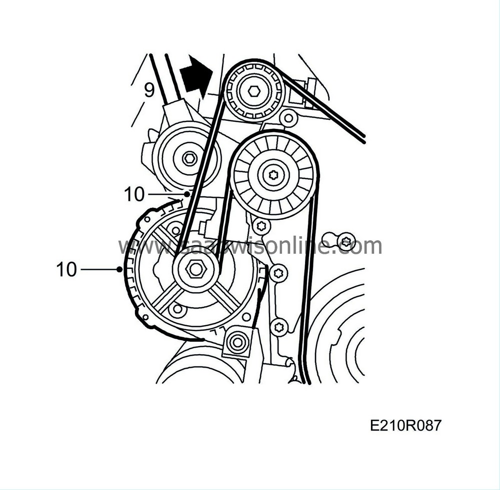
Relieve the belt tensioner with tool 83 95 254 and insert a 3 mm Allen key in the hole. Remove the multigroove V-belt.
|
Important
|
|
Be careful so that the belt tensioner does not crack at its end position!
|
|
|
|
|
10.
|
Remove the belt tensioner, loosen and move aside the generator. Remove the generator bracket.
|
|
11.
|
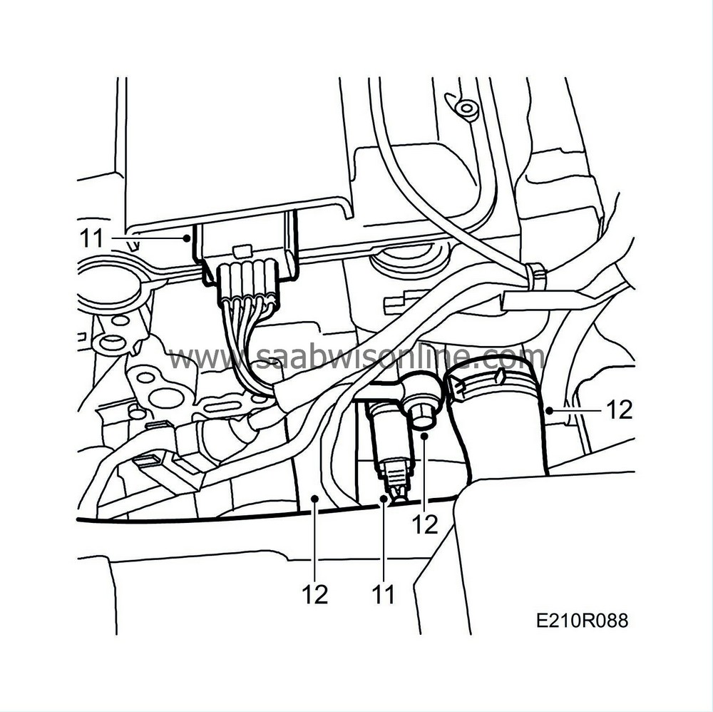
Unplug the temperature sensor and ignition discharge module connectors.
|
|
12.
|
Disconnect the coolant hoses from the cylinder head.
|
|
13.
|
Remove the cover from the throttle body lever. Remove the throttle cable and the dipstick with tube, and undo the fuel hoses using tool 83 94 702.

|
|
14.
|
Remove the crankcase breather nipple from the timing cover.
|
|
15.
|
Raise the car and remove the intake manifold steady bar.

|
|
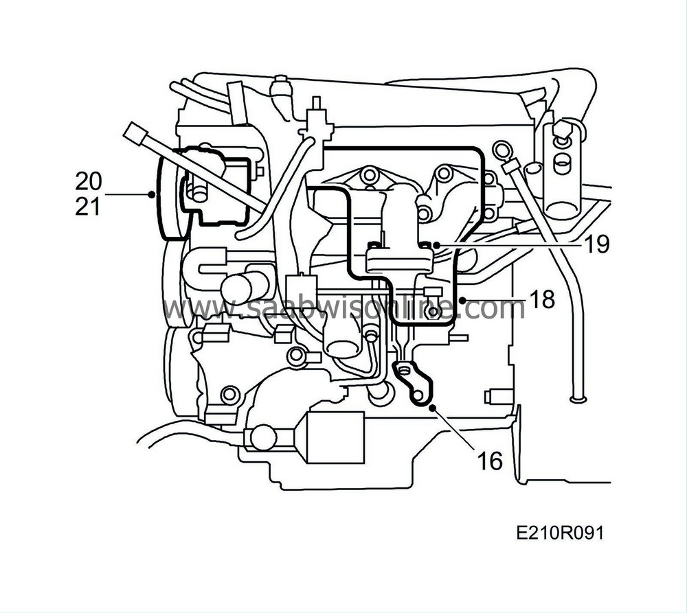
16.
|
Remove the turbocharger steady bar.
|
|
17.
|
Lower the car to the floor.
|
|
18.
|
Remove the heat shield over the turbocharger and exhaust manifold. Two clips at top and a nut at bottom.
|
|
19.
|
Remove the four retaining nuts between the exhaust manifold and the turbocharger. Heat them carefully if they stick.
|
|
20.
|
Remove the power steering pump and lay it on the radiator crossmember.
|
|
21.
|
Remove the lower screw from the steering servo pump bracket.
|
|
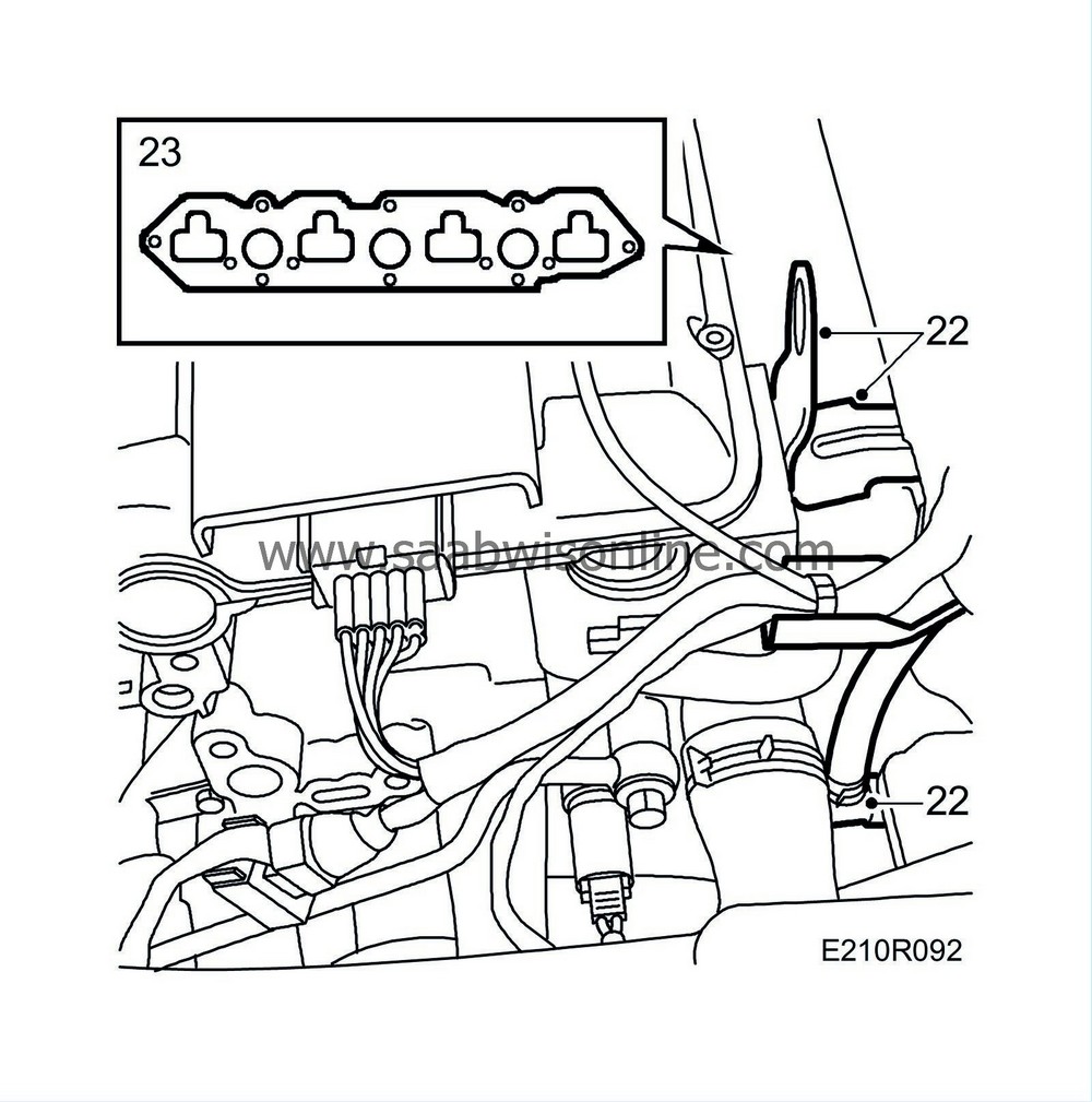
22.
|
Remove the bracket for the ignition discharge module electrical connections from the rear lifting eye and the mounting for the heat exchanger pipe.
|
|
23.
|
Remove the intake manifold with partition and move it rearwards towards the bulkhead wall. (The lower/centre retaining bolts may be more easily accessible from underneath.) (Leave the intake manifold in the car.)
|
|
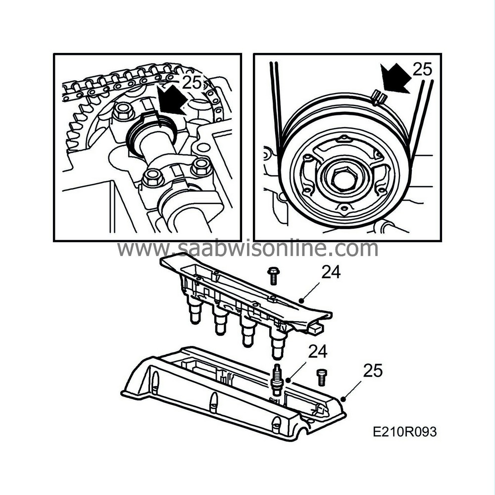
24.
|
Remove the ignition discharge module and spark plugs.
|
|
25.
|
Remove the camshaft cover, line up the crankshaft pulley's mark with the timing cover and check that the camshafts are in line with their timing marks.
|
|
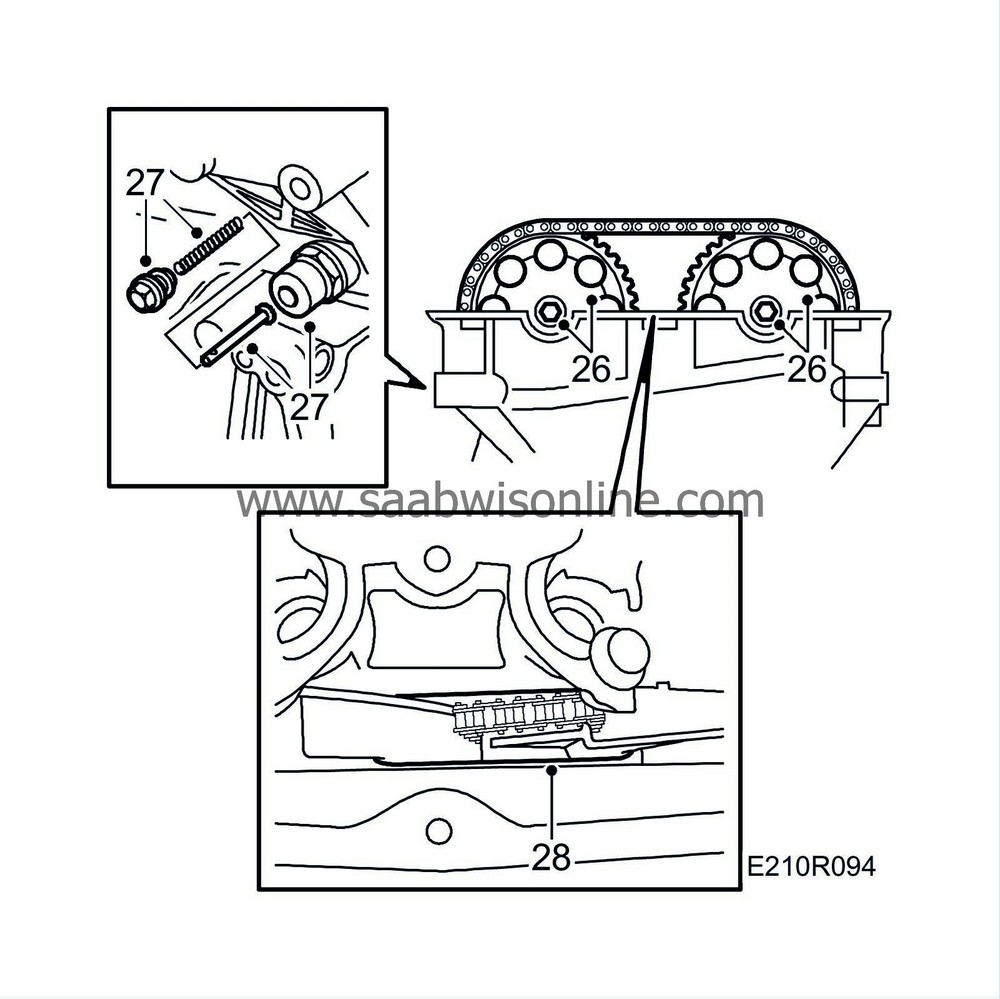
26.
|
Undo the camshaft sprocket bolts. Hold the end of the camshaft with a spanner to prevent it from turning.
|
|
27.
|
Undo the bolt on the idler pulley and remove the chain tensioner. A 27 mm socket can be used after removing the plug with spring and pushrod.
|
|
28.
|
Remove the camshaft sprockets and fit a rubber band between the chain guides.
|
|
29.
|
Remove the cylinder head. Start with the bolts in the timing cover and proceed in reverse order to fitting. Use a pair of pliers or a magnet to retrieve the bolts.
|
|
30.
|
Wipe up any oil that has run out. Make sure that the timing chain does not obstruct its removal and then lift off the cylinder head.

|
|
Removal of the valve gear
|
|
Important
|
|
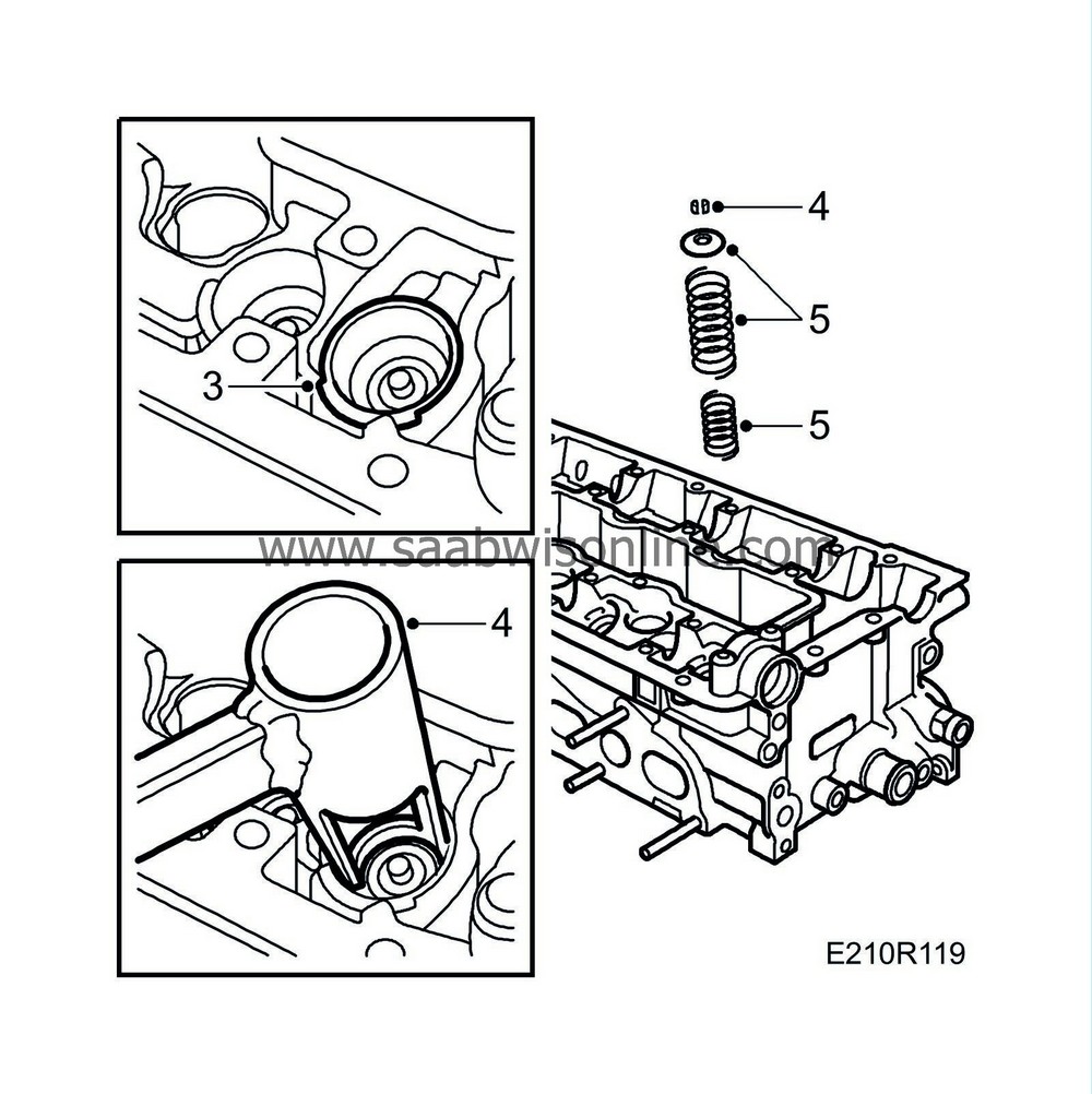
The cylindrical surfaces around the valve springs are sliding surfaces for the tappets and must not be scratched or scored. Therefore, fit protective collars 83 93 746 to protect the tappet guide cylinders.
|
|
|
|
1.
|
Remove the camshaft bearing caps. It is important to finish with the bearing cap on the tappets that are under pressure. Lift out the camshafts.

|
|
2.
|
Remove the tappets and place them in valve stand 83 93 787.
|
|
3.
|
Fit the protective collars 83 93 746.
|
|
4.
|
Use valve spring compressor 83 93 761 and valve spring depressor 83 93 779 and remove the valve cones.
|
|
5.
|
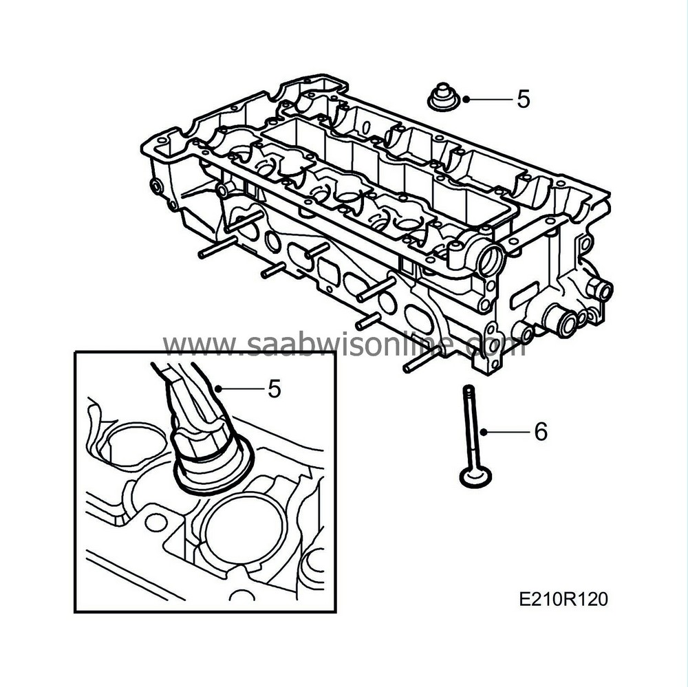
Lift out the spring cap and valve spring. Lift out the washer with valve guide seal using pliers 83 94 157.
|
|
6.
|
Remove the valves and place them in valve stand 83 93 787.
|
|
7.
|
Place the cylinder head in a jig and remove the thermostat.
|
|
1.
|
Clean the combustion chamber and valve seats. Use a rotating wire brush for example. Wash the cylinder head.
|
|
2.
|
Refit the intake valves and fit new exhaust valves. Fill the intake and exhaust chambers with methanol. Do not spill.
|
|
3.
|
Check all valves for leaks. The fluid may dampen but not run. If no leaks are detected, fit the cylinder head according to the relevant directions.
|
|
Valve seats, machining and grinding
|
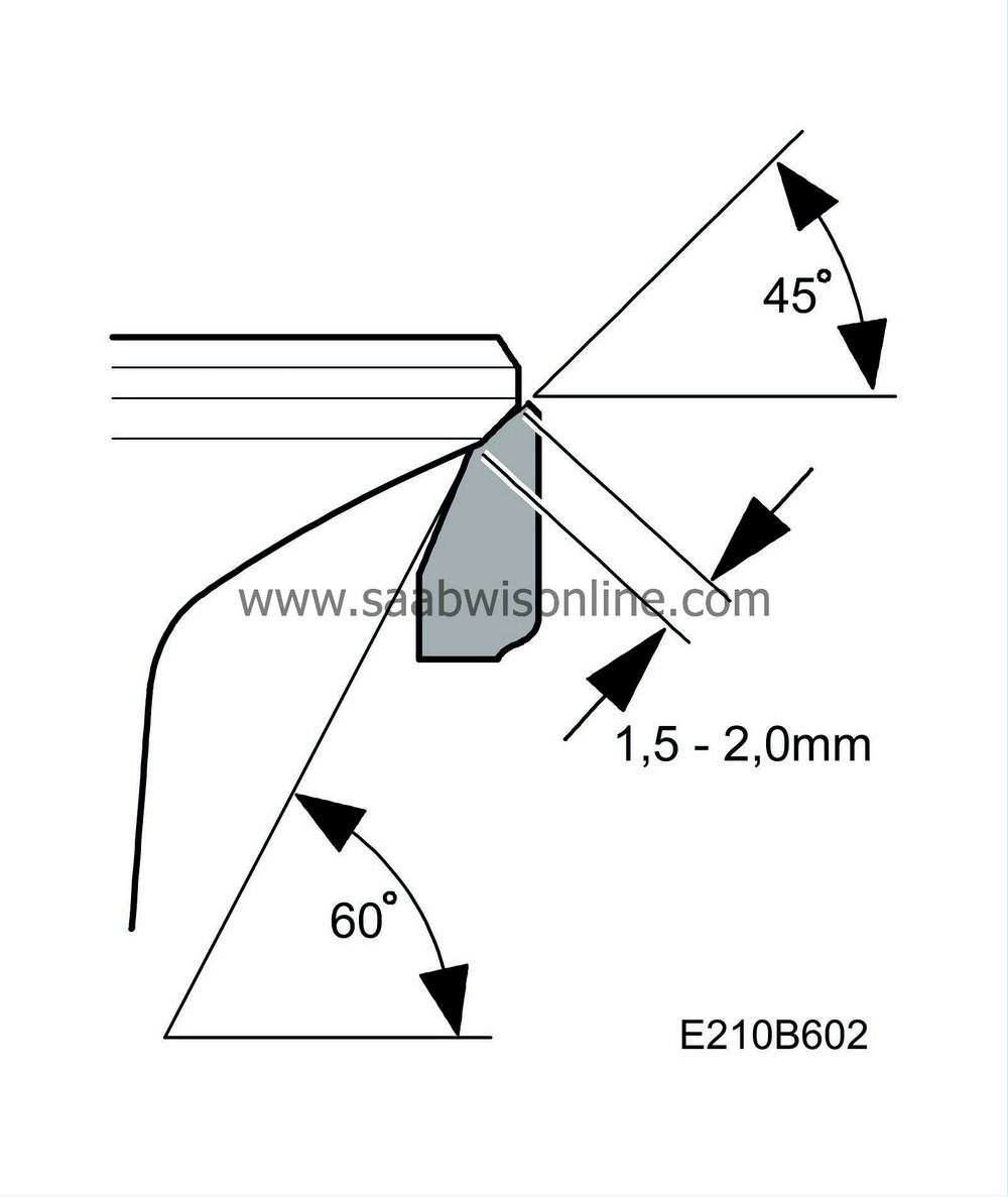
For machining, use a valve cutter set with T-handle,
guide spindle 83 95 204, valve cutter 83 93 936 (60°) and 78 61 040 (45).
Valve seat angles, inlet and exhaust valves: 45°.
Correction angle: 60°. Valve seat width:
Inlet valve 1.0-1.5 mm
Outlet valve 1.5-2.0 mm
|
1.
|
Press home the guide spindle into the valve guide from the valve seat side. Cut clean the valve seats in the cylinder head with a 45° cutter. It may be necessary to remove the hard surface on the exhaust valve seat with an abrasive cloth. In most cases, the valve seat width will be too great after cutting and must be reduced. Use a 60° correction cutter to reduce the width.

|
|
2.
|
Apply a thin layer of grinding paste to the valve seat and insert the valve into the cylinder head. Do not get grinding paste on the valve stem. Perform a few grinding movements with the grinding tool. Clean off the grinding paste thoroughly from the seat and check the surface contact with marker ink for example. Regrind if required and then perform subsequent cutting if necessary.
|
Important
|
|
Clean off all grinding paste thoroughly after machining and ensure that no paste reaches the valve guide.
|
|
|
|
|
Checking valve clearances
|
This method presupposes that the cylinder head has been removed.
Check and adjust the valve clearance relative to the working range of the tappet.
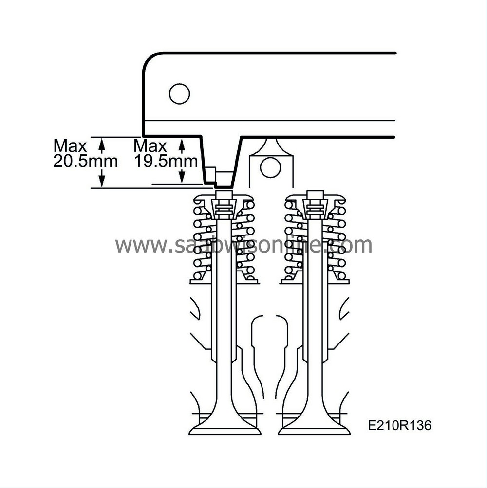
The tolerances for checking valve clearance are 19.5±0.05 mm minimum and 20.5±0.05 mm maximum.
The valve clearance settings are 20.0 minimum and 20.4 maximum, with a nominal clearance of 20.2 mm.
Valve clearance is equivalent to the distance between the end of the valve stem and the camshaft bearing seat.
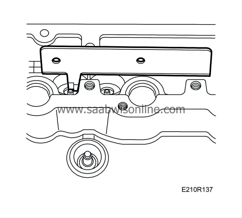
Before valve clearances can be checked, the camshafts and valve tappets must first be removed. Valve clearance is checked with valve clearance gauge 83 93 753 as follows:
|
1.
|
Place the valve clearance gauge across two of the camshaft bearing seats with the depth gauge against the end of the valve stem.
|
|
2.
|
Check that the maximum gauge depth of 20.5 mm actually reaches down to the end of the valve stem (noticed by the valve clearance gauge not bottoming against the bearing seat closest to the depth gauge).
|
|
3.
|
Then check that the min depth 19.5 mm does not reach the end of the valve stem spindle. Correct valve position should be between the depth measurement min and max values. If the valve position deviates from the given measurements, adjustments are done on the valve spindle or valve seat. The valve spindle is shortened if measurement is below the min value and the valve seat is machined if the max value is exceeded. When adjusting the valve position, set this at nominal value 20.2 mm.
|
|
Important
|
|
Replace defective valve-stem seals and lubricate sealing surfaces and bearings before fitting the valves. Raise the cylinder head on blocks to avoid bending the valves when the camshafts are turned.
|
|
|
|
1.
|
Fit the washer with valve-stem seal using pliers 83 94 157. Fit the thermostat.

|
|
2.
|
Fit the valves and springs.
|
|
3.
|
Use valve spring compressor 83 93 761 and valve spring depressor 83 93 779 and refit the valve cones.

|
|
4.
|
Place the valve clearance gauge 83 93 753 across two of the camshaft bearing seats with the depth gauge against the end of the valve stem.
|
|
5.
|
Check that the max. depth gauge of 20.5 mm reaches down to the end of the valve stem (clearance gauge does not bottom in the bearing seat closest to the depth gauge).
|
|
6.
|
Then check that the minimum gauge depth of 19.5 mm does not reach down to the end of the valve stem. The correct valve clearance is between the minimum and maximum gauge depths. If the clearance is less than the minimum, the valve stem must be shortened and if it is greater than the maximum the valve seat must be reground.
|
|
7.
|
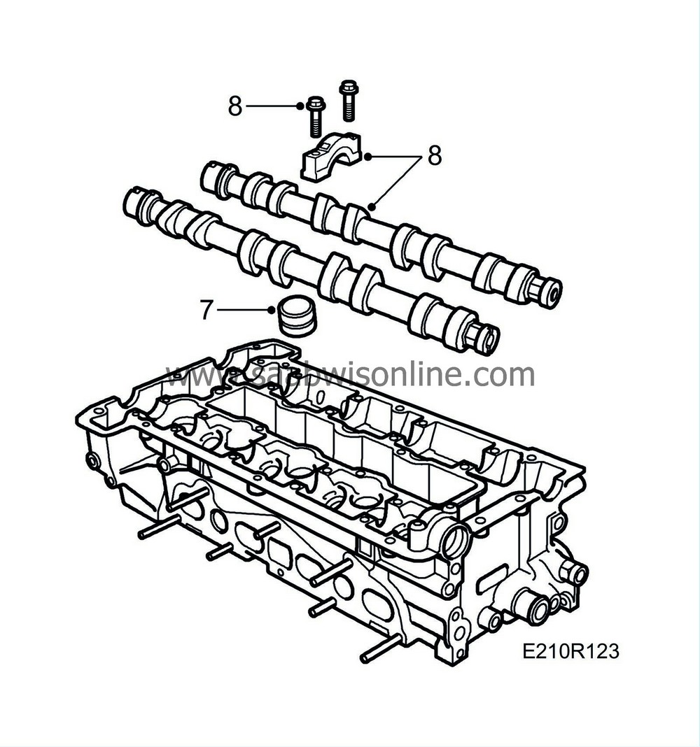
Remove the protective sleeves and fit the valve tappets.
|
|
8.
|
Fit the camshafts and bearing caps, starting where the cams point downwards and press on the tappets. Bearing caps marked 1-5 are for the inlet side, 6-10 for the exhaust side.
Tightening torque 15 Nm (11 lbf ft).
|
Important
|
|
The black bolts have an oilway and should be fitted on the spark plug side.
|
|
|
|
|
9.
|
Line up the marks on the camshafts with their timing marks.
|
|
Fitting of cylinder head (in car)
|
|
1.
|
Fit the inner gasket for the cylinder head intermediate partition with gasket sealing compound.
|
|
2.
|
Position the gasket between the intake manifold and intermediate partition by means of two straps.
|
|
3.
|
Thoroughly clean all gasket surfaces. Apply a 2 mm thick and 10-20 mm long bead of Loctite 518, part no. 93 21 795, on the inner section of the transmission cover mating face (towards the cylinder head). Fit the cylinder head gasket. Turn the crankshaft 45° in the rotational direction of the engine and fit the cylinder head. Make sure that it enters the locating sleeves correctly and that the chain is in the clear.

|
|
4.
|
Fit the 10 Torx screws and tighten them, using a torque wrench.
Tightening torque in three stages,
- Step I: 40 Nm (30 lbf ft)
- Step II: 60 Nm (44 lbf ft)
- Step III: Tighten a further 90°
Tightening sequence for the cylinder head bolts as shown.
|
|
5.
|
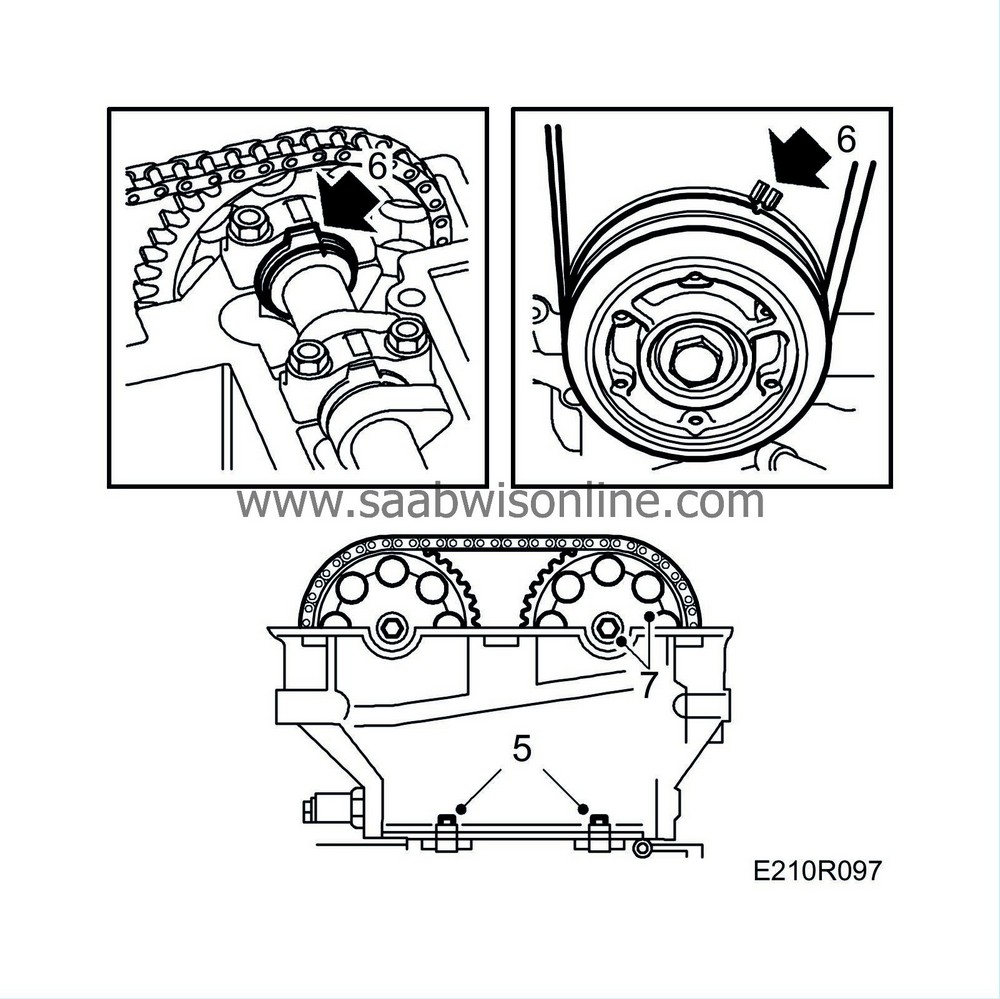
Fit the two screws between the timing cover and the cylinder head.
Tightening torque 22 Nm (16 lbf ft).
|
|
6.
|
Check that the camshafts are in line with their timing marks and reset the crankshaft in line with the 0 mark.
|
|
7.
|
Fit the camshaft sprockets and chain. Start with the camshaft on the exhaust side.
Do not tighten the bolts yet!
|
|
8.
|
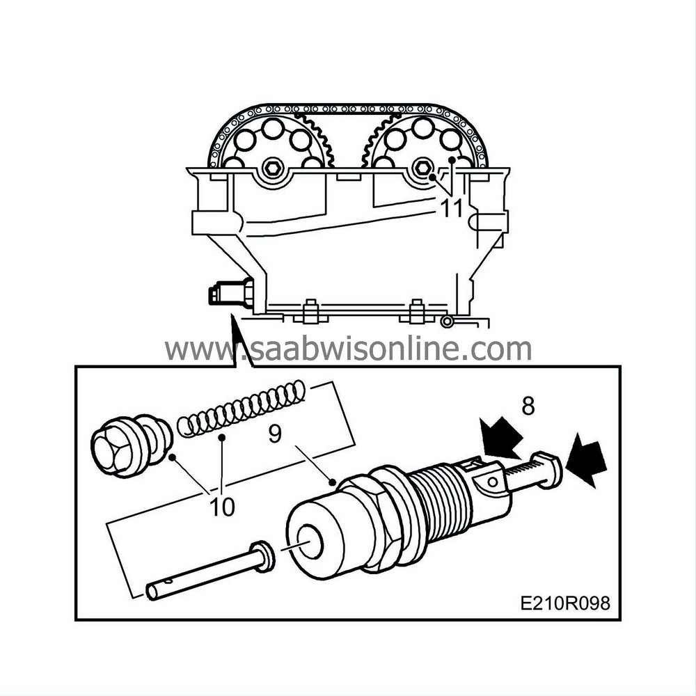
Prepare the chain tensioner for mounting by pressing down the catch and pressing in the chain tensioner.
|
|
9.
|
Fit the chain tensioner, using a 27 mm socket.
Tightening torque 63 Nm (47 lbf ft).
|
|
10.
|
Fit the chain tensioner plug with push rod and spring.
Tightening torque 22 Nm (16 lbf ft).
|
|
11.
|
Tighten the bolt on the idler pulley. Tighten the camshaft sprocket bolts. Hold the end of the camshaft with a spanner.
Tightening torque 63 Nm (47 lbf ft).
|
|
12.
|
Check that the chain is correctly seated in the guides. Rotate the crankshaft two complete turns and check the settings of the crankshaft pulley and camshafts.
|
|
13.
|
Clean the sealing surface of the camshaft cover with benzene. If changing the gaskets, apply a thin layer of gasket adhesive, part no. 46 20 084 to the inner and outer gaskets.
|
|
14.
|
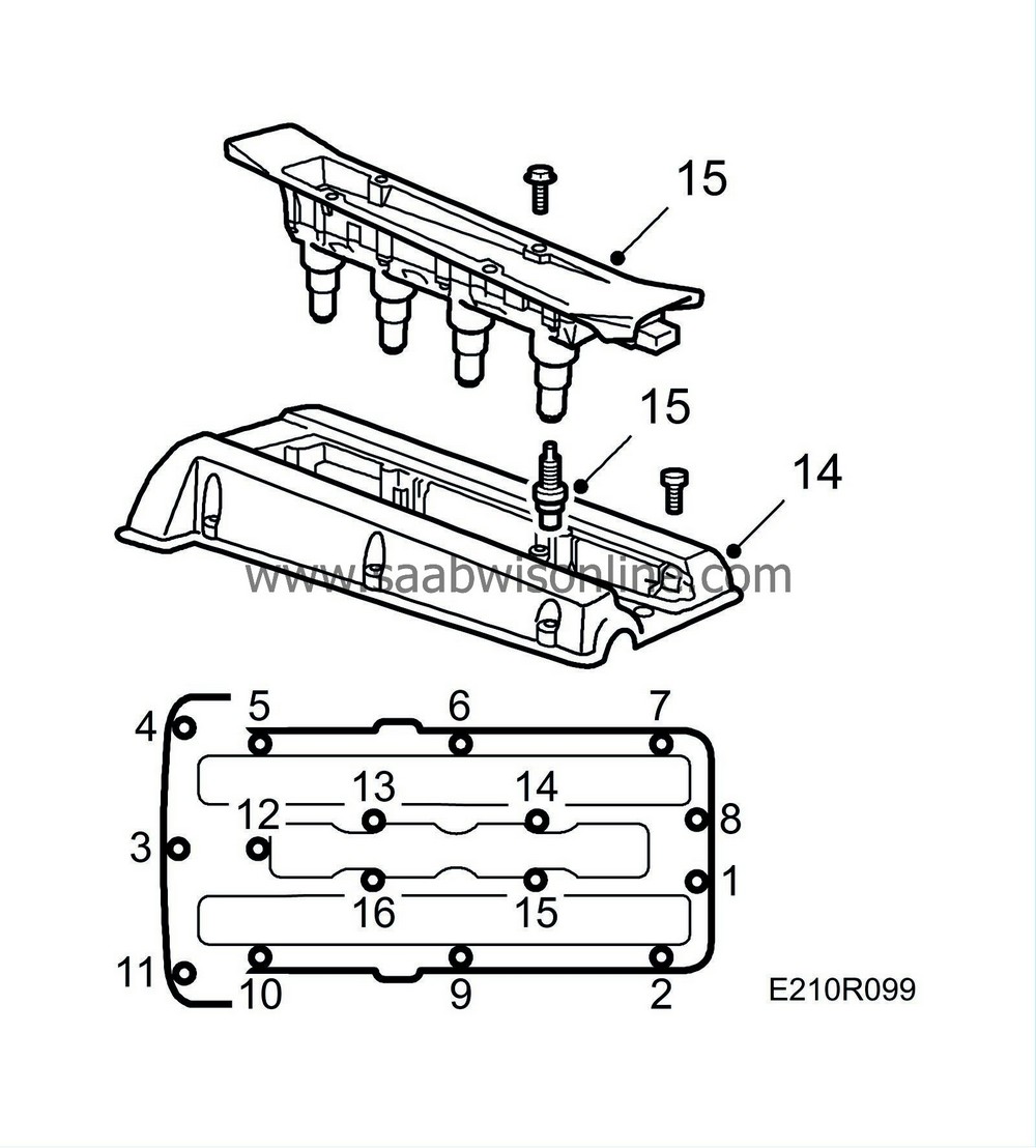
Coat the opening in the camshaft cover thinly with oil and fit the cover, starting at the opening. Make sure that the cables at the edge of the cover against the intake manifold do not get trapped. Then tighten the bolt located furthest to the front at the timing chain end. After that, continue all the way round on both the inside and outside.
Tightening torque 15 Nm (11 lbf ft).
|
|
15.
|
Fit the spark plugs.
Tightening torque 28 Nm (21 lbf ft).
Fit the ignition discharge module.
Tightening torque 11 Nm (8 lbf ft).
|
|
16.
|
Fit the intake manifold with intermediate partition but do not tighten until the straps are cut off and pulled away.
|
|
17.
|
Tighten the intake manifold, using a torque wrench.
Tightening torque 22 Nm (16 lbf ft).

|
|
18.
|
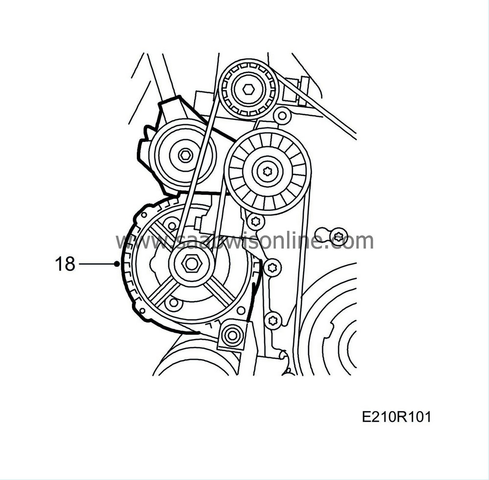
Fit the generator bracket. Make sure that the adjuster sleeves in the generator bracket is tapped out approx. 1 mm to facilitate fitting. Fit the belt tensioner.
|
|
19.
|
Tighten the bracket for the ignition discharge module's connector in the rear lifting eye and the water pipe fitting.

|
|
20.
|
Fit the bolt securing the water pipe to the thermostat housing cover.
|
|
21.
|
Connect the coolant hoses to the cylinder head.
|
|
22.
|
Plug in the ignition discharge module and temperature sensor connectors.
|
|
23.
|
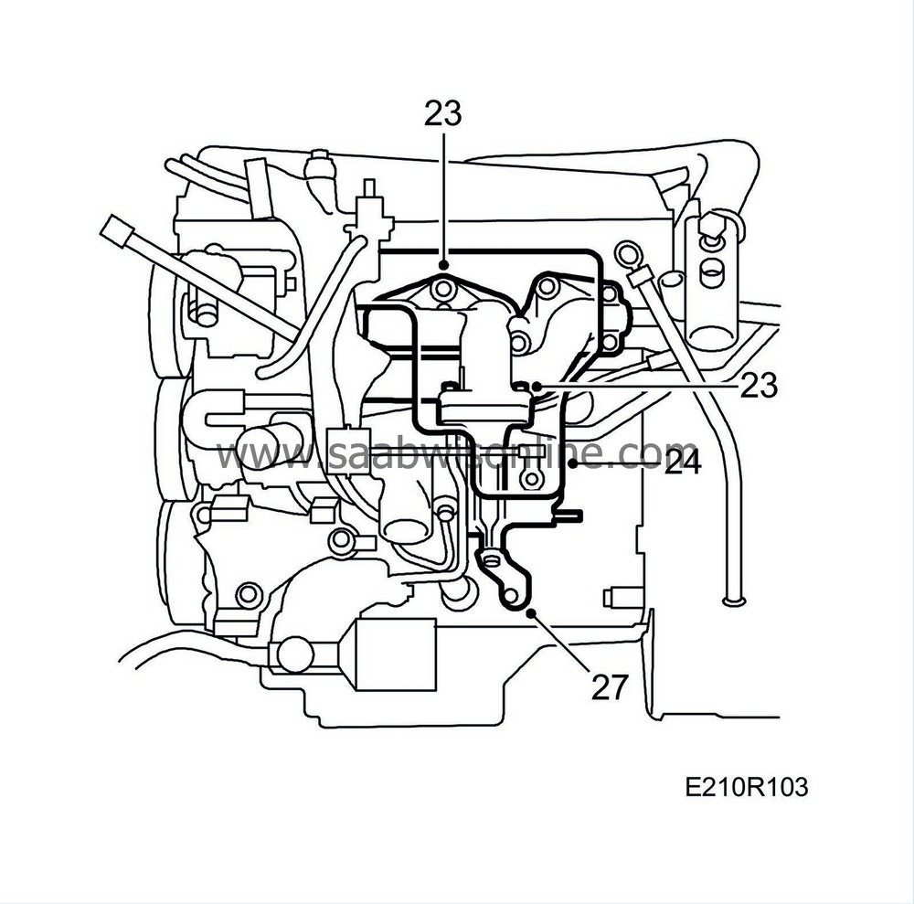
Fit and tighten the turbocharger retaining nuts between the exhaust manifold and the turbocharger.
Tightening torque 25 Nm (19 lbf ft).
|
|
24.
|
Fit the heat shield over the turbocharger.
|
|
25.
|
Insert the dipstick tube.
|
|
27.
|
Tighten the turbocharger steady bar retaining bolts.
|
|
28.
|
Tighten the intake manifold steady bar retaining bolts. Fit the dipstick tube correctly in position.

|
|
29.
|
Lower the car to the floor.
|
|
30.
|
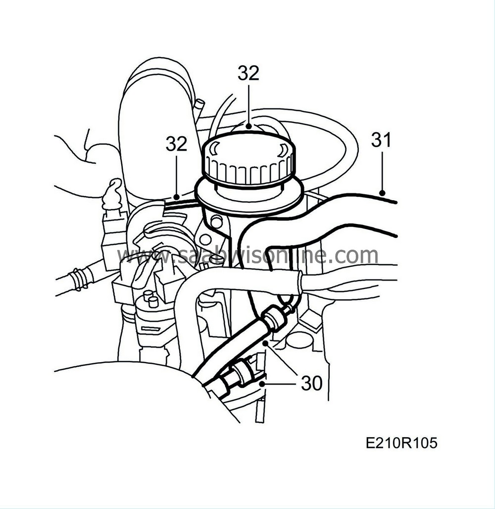
Fit the fuel hoses and rubber protectors.
|
|
31.
|
Fit the crankcase ventilation nipple on the valve cover.
|
|
32.
|
Tighten the dipstick tube, and fit the accelerator cable and ground connections to the cylinder head. Fit the cover over the throttle body spindle.
|
|
33.
|
Fit the servo pump. Fit the multigroove belt and check the position of all pulleys.
Tightening torque 20 Nm (15 lbf ft).
|
|
34.
|
Relieve the belt tensioner with reliever 83 95 254 and remove the Allen key.

|
|
35.
|
Fit the lifting eye, press the rubber in position and plug in the solenoid valve's connector.

|
|
36.
|
Fit the pressure pipe and bypass valve and connect the valve's vacuum hose.
|
|
37.
|
Fit and connect the mass air flow sensor's rubber gaiter.
|
|
38.
|
Fit the engine mounting complete with yoke and servo pump pipe bracket, and tighten it using a torque wrench.
Tightening torque bolts 47 Nm (39 lbf ft)
Tightening torque nut 105 Nm (78 lbf ft)
|
|
39.
|
Remove the wedge and secure the servo pump pipe to the subframe.
|
|
40.
|
Fit the right-hand front wheel.
Tightening torque 110 Nm (80 lbf ft)
|
Important
|
|
The wheels must be hanging freely when the wheel bolts are tightened.
|
|
|
|
|
41.
|
Fit the crankcase breather pipe.
Tightening torque, banjo connection 24 Nm (18 lbf ft)
Tightening torque mounting against camshaft cover 11 Nm (8 lbf ft)
|
|
42.
|
Connect the negative battery cable, check that the radiator's drain plug is properly tightened, top up with coolant and check the system for leaks.
|
|
43.
|
Check the coolant and engine oil levels and top up as necessary.
|
|
44.
|
Remove the protective covers from the wings and check that the engine bay is clean.
|
|
45.
|
Lower the car. Bleed the system as follows.
|
|
46.
|
Fill with coolant. Do not forget to shut the drain valve on the radiator first. Close the cap
|
|
47.
|
Start the engine and run it warm with the heater control on max.
|
|
48.
|
Check the coolant level. Top up if necessary.
|
|
49.
|
Check all functions. Test drive the car. Reset the clock and radio code. Calibrate the ACC.
|
|
Warranty/Time information
|
Failed Object: 21412
Fault/Reason code: 71
Location code: 09 (US: 5)
Warranty Type (US): 01
Repair/Action code: 01 and 08
Labour Operation (US): 21409 (CA J0518)
Time: 8.9 h


