
Test readings, control module connections
| Test readings, control module connections |
| Scope |
Readings and directions for measuring control module voltage levels can be found under this heading.
| Remember: |
| • |
Note the test conditions and use common sense when assessing the test result.
|
|
| • |
The specified readings are with the ignition in position ON unless otherwise stated.
|
|
| • |
First check that the control module has a power supply and is grounded.
|
|
| • |
Then check all sensor inputs and signals from other systems.
|
|
| • |
Finally, check the control module outputs. Remember that the readings do not determine whether the actuator is working.
|
|
| • |
If any reading is not OK, consult the wiring diagram to trace the leads, connectors or components which should be checked more thoroughly.
|
|
| • |
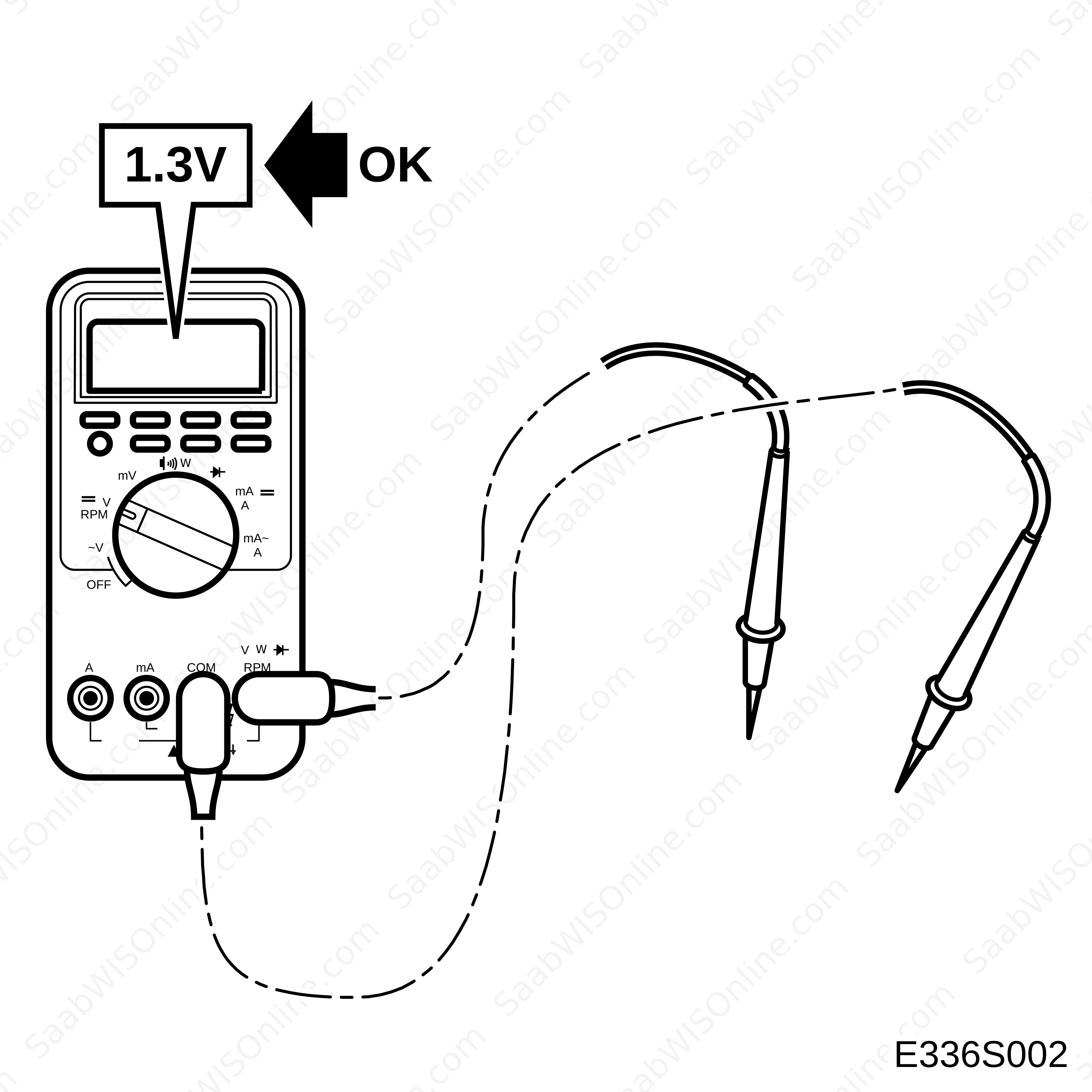
The specified test readings refer to those obtained with a calibrated Fluke 88/97.
|
|
| • |
Test readings in % (+) and ms (+) show the pulse ratio and pulse duration of the signal. A test instrument capable of giving pulse ratio and pulse duration readings must be used. The (+) sign indicates a positive trigger pulse, TRIG+.
|
|
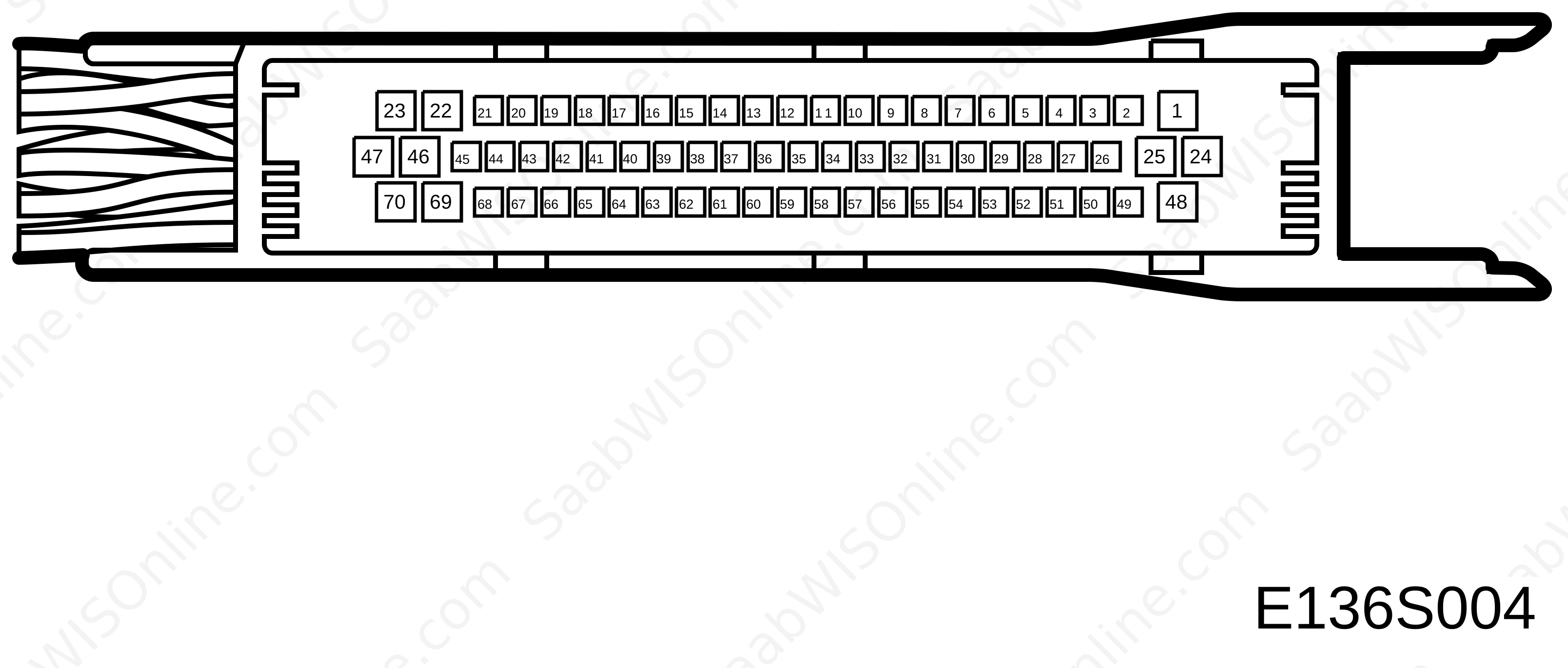
| Control module connector |
|
Pin No.
|
Cable colour
|
Component/
function |
In/Out
|
Test conditions
|
Across
|
Test reading
|
See
|
|
1
|
YE/RD
|
Courtesy / floor lighting
|
Out
|
Door open
|
1-57
|
B+
|
Lighting and signalling systems

|
|
2
|
BU/WH
|
Luggage compartment lighting
|
Out
|
Boot lid/tailgate open
|
2-57
|
B+
|
Lighting and signalling systems
|
|
3
|
BU/RD
|
Hazard flashers, switch
|
In
|
Switch depressed (closed)
|
3-26
|
B+
|
Lighting and signalling systems
|
|
4
|
GN/GY
|
Dipped beam relay
|
Out
|
Light switch in pos. 2.
Ignition ON |
4-26
|
B+
|
Lighting and signalling systems
|
|
5
|
WH
|
I-bus (-)
|
In/Out
|
Bus active
|
5-57
|
2-3V
|
|
|
6
|
|
No connection
|
|
|
|
|
|
|
7
|
OG
|
Ignition +B, logic
|
In
|
Key turned in ignition switch
|
7-57
|
B+
|
,
|
|
8
|
|
No connection
|
|
|
|
|
|
|
9
|
BU/GN
|
A/C pressure sensor in
|
In
|
Ignition ON
|
9-54
|
0.4-4.6 V (2-30 bar)
|
Heating and ventilation, A/C
|
|
10
|
BU/WH
|
Evaporation temperature sensor. Power supply
|
In
|
Ignition ON
|
10-30
|
6°C = 2.8-3.7V
|
Heating and ventilation, A/C
|
|
11
|
OG/WH
|
Main beam relay
|
Out
|
Main beam, light switch in pos. 2.
Ignition ON |
11-26
|
B+
|
Lighting and signalling systems
|
|
12
|
YE/RD
|
Rear window intermittent wiper, relay
|
Out
|
Activate with diagnostic instrument
|
12-26
|
B+
|
Wash/wipe systems
|
|
13
|
|
No connection
|
|
|
|
|
|
|
14
|
GN
|
I-bus (+)
|
In/Out
|
Bus active
|
14-57
|
2-3V
|
|
|
15
|
BU/YE
|
Light switch, pos. 2
|
In
|
Light switch in pos. 2.
Ignition ON |
15-57
|
B+
|
Lighting and signalling systems
|
|
16
|
BK/RD
|
Rear fog lights, switch
|
In
|
Light switch in pos. 2.
Ignition ON. Hold switch depressed (closed) |
16-57
|
B+
|
Lighting and signalling systems
|
|
17
|
|
No connection
|
|
|
|
|
|
|
18
|
GN/YE
|
Electrically heated rear window from MCC
|
In
|
Hold switch depressed (closed)
|
18-57
|
B+
|
Glass, windows and mirrors
|
|
19
|
RD/BK
|
Rear window intermittent wiper, switch
|
In
|
Ignition ON. Switch in intermittent position.
|
19-57
|
B+
|
Wash/wipe systems
|
|
20
|
WH
|
Direction indicators LH, switch
|
In
|
Switch to the left.
|
20-57
|
B+
|
Lighting and signalling systems
|
|
21
|
GN
|
Intermittent wiper, switch
|
In
|
Ignition ON. Switch in intermittent position.
|
21-57
|
B+
|
Wash/wipe systems
|
|
22
|
RD
|
Direction indicators, power supply +30
|
In
|
Always +30.
|
22-57
|
B+
|
Lighting and signalling systems
|
|
23
|
GN/RD
|
Interior lighting
|
Out
|
Door open
|
23-57
|
B+
|
Lighting and signalling systems
|
|
24
|
RD
|
Comfort lighting in cabin, power supply +30
|
In
|
Always +30
|
24-57
|
B+
|
|
|
25
|
RD/WH
|
Rear fog light, lamp
|
Out
|
Light switch in pos. 2.
Ignition ON. Hold switch depressed (closed). |
25-57
|
B+
|
Lighting and signalling systems
|
|
26
|
RD
|
DICE, power supply +30
|
In
|
Always +30
|
26-57
|
B+
|
|
|
27
|
YE
|
Headlamp wiper, relay
|
Out
|
Activate with diagnostic instrument.
|
26-27
|
B+
|
Wash/wipe systems
|
|
28
|
BU
|
Diagnostics KW 2000
|
In/Out
|
Communication with DICE or a bus system
|
28-57
|
11V
|
,
|
|
29
|
GN
|
Front fog lights, relay
|
Out
|
Market dependent or activate with diagnostics tool.
|
26-29
|
B+
|
Lighting and signalling systems
|
|
30
|
GN/RD
|
Evaporator temperature sensor, ground
|
In
|
Always
|
26-30
|
B+
|
Heating and ventilation, A/C
|
|
31
|
VT
|
Ignition +54, logic
|
In
|
Key in “ON” position
|
31-57
|
B+
|
|
|
32
|
|
No connection
|
|
|
|
|
|
|
33
|
GN/GY
|
Intermittent wiper potentiometer, ground
|
In
|
Always
|
26-33
|
B+
|
Wash/wipe systems
|
|
34
|
|
No connection
|
|
|
|
|
|
|
35
|
RD/WH
|
Radiator fan, low speed, relay
|
Out
|
Activate with diagnostic instrument
|
26-35
|
B+
|
Cooling system
LINK.
|
|
36
|
|
No connection
|
|
|
|
|
|
|
37
|
|
No connection
|
|
|
|
|
|
|
38
|
BU/YE
|
A/C pressure sensor, power supply
|
Out
|
Ignition ON
|
38-57
|
5V
|
Heating and ventilation, A/C
|
|
39
|
PK
|
Light switch in zero position
|
In
|
Light switch in zero position. Ignition ON
|
39-57
|
B+ (fuse 35 fitted)
0V (fuse 35 not fitted) |
Lighting and signalling systems
|
|
40
|
|
No connection
|
|
|
|
|
|
|
41
|
BK/VT
|
Main/dipped beam
|
In
|
Move stalk switch to farthest position
|
41-57
|
B+
|
Lighting and signalling systems
|
|
42
|
GY/WH
|
Rear window washer, switch
|
In
|
Ignition ON. Switch activated.
|
42-57
|
B+
|
Wash/wipe systems
|
|
43
|
|
No connection
|
|
|
|
|
|
|
44
|
YE
|
Direction indicators RH, switch
|
In
|
Switch to the right
|
44-57
|
B+
|
Lighting and signalling systems
|
|
45
|
GN
|
Reversing-light switch
|
In
|
Reverse gear selected
|
45-57
|
B+
|
Lighting and signalling systems
|
|
46
|
RD
|
Map/cabin lighting, power supply +30
|
In
|
Always +30
|
46-57
|
B+
|
Lighting and signalling systems
|
|
47
|
YE/GY
|
Direction indicators RH, lamp
|
Out
|
Switch to the right
Ignition ON |
47-57
|
B+
|
Lighting and signalling systems
|
|
48
|
RD
|
Rear fog light, power supply +30
|
In
|
Always +30
|
48-57
|
B+
|
Lighting and signalling systems
|
|
49
|
BU/WH
|
Button illumination
|
Out
|
Light switch in pos. 2.
Ignition ON. Rheostat in max. position. |
49-57
|
PWM 3.5V to B+
|
Lighting and signalling systems
|
|
50
|
|
No connection
|
|
|
|
|
|
|
51
|
GN/WH
|
Radiator fan, high, relay 2
|
Out
|
Activate with diagnostic instrument
|
26-51
|
B+
|
Cooling system
|
|
52
|
BU/WH
|
Electrically heated rear window, relay
|
Out
|
Ignition ON. Hold switch depressed (closed).
|
26-52
|
B+
|
Glass, windows and mirrors
|
|
53
|
GY/WH
|
Radiator fan, high, relay 1
|
Out
|
Activate with diagnostic instrument.
|
26-53
|
B+
|
Cooling system
|
|
54
|
OG
|
A/C pressure sensor, ground
|
In
|
Always
|
26-54
|
B+
|
Heating and ventilation, A/C
|
|
55
|
WT/WH
|
Intermittent wiper, rheostat
|
In
|
Ignition ON
|
55-57
|
2 sec: 0V 15 sec: 6.3V
|
Wash/wipe systems
|
|
56
|
|
No connection
|
|
|
|
|
|
|
57
|
BK
|
ground
|
In
|
Always
|
57-B+
|
B+
|
|
|
58
|
BU/RD
|
Intermittent wiper, relay
|
Out
|
Activate with diagnostic instrument.
|
58-B+
|
B+
|
Wash/wipe systems
|
|
59
|
|
No connection
|
|
|
|
|
|
|
60
|
|
No connection
|
|
|
|
|
|
|
61
|
|
No connection
|
|
|
|
|
|
|
62
|
BU
|
Front fog lights, switch
|
In
|
Ignition ON. Hold switch depressed (closed).
|
62-57
|
B+
|
Lighting and signalling systems
|
|
63
|
YE/BK
|
Front wiper, park position
|
In
|
Windscreen wiper not in parked position.
Ignition ON |
63-57
|
B+
|
Wash/wipe systems
|
|
64
|
BU/RD
|
Ignition +15, logic
|
In
|
Ignition ON
|
64-57
|
B+
|
|
|
65
|
GN/WH
|
A/C request MCC
|
In
|
Ignition ON
Hold A/C switch depressed (closed). |
65-57
|
B+
|
Heating and ventilation, A/C
|
|
66
|
|
No connection
|
|
|
|
|
|
|
67
|
|
No connection
|
|
|
|
|
|
|
68
|
YE
|
Windscreen washers, switch
|
In
|
Ignition ON. Switch activated.
|
68-57
|
B+
|
Wash/wipe systems
|
|
69
|
YE/WH
|
Direction indicators LH, lamp
|
Out
|
Ignition ON. Switch to the left.
|
69-57
|
B+
|
Lighting and signalling systems
|
|
70
|
RD/WH
|
Reading lamp
|
Out
|
Ignition ON
|
70-57
|
B+
|
Lighting and signalling systems
|
This project is supported by memberships and donations. If you use this site, please consider Joining SCNA and/or making a donation.
Our Friends