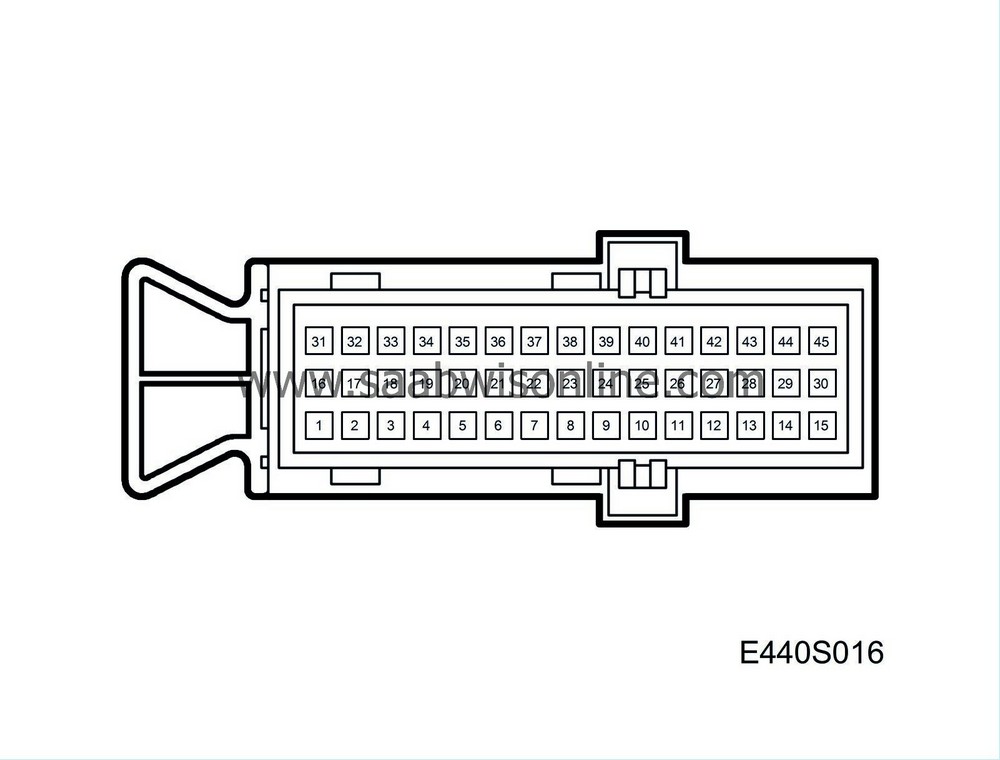
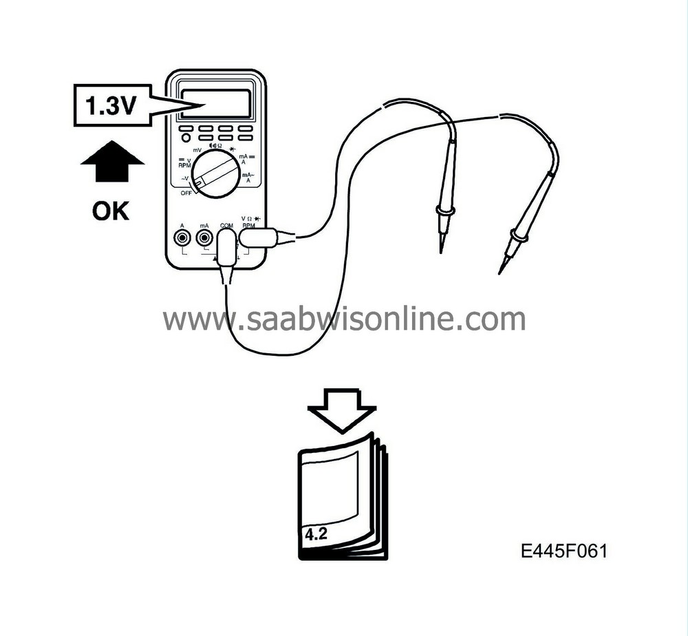
Pin
|
Cable colour
|
Component/ Function
|
In/Out
|
Test conditions
|
Test between
|
Test reading
|
See
|
1
|
BU/RD
|
Battery voltage (+15 circuit)
|
In
|
Ignition ON
|
1-B+
|
< 0.5 V
|

|
2
|
WH/GN
|
Solenoid, Lock-up (SL)
|
Out
|
Ignition ON
Activate with diagnostics instrument
SOLENOID LOCK-UP
|
2-32
|
ON=B+
OFF=0 V
|

|
3
|
|
No connection
|
|
|
|
|
|
4
|
WH/YE
|
Solenoid 2-3 (S2)
|
Out
|
Ignition ON
Gear D
Winter mode ON
Winter mode OFF
|
4-32
|
0 V
B+
|

|
5
|
|
No connection
|
|
|
|
|
|
6
|
GN
|
NTC sensor for transmission fluid temperature
|
In
|
Ignition ON
20°C
50°C
80°C
|
6-32
|
2.3 V
1.7 V
1.0 V
|

|
7
|
BU
|
Switch, SPORT
|
In
|
Ignition ON
Switch activated
Switch not activated
|
7-32
|
0 V
B+
|

|
8
|
|
No connection
|
|
|
|
|
|
9
|
GN
|
Bus+
|
In/Out
|
Ignition ON
|
9-32
|
approx. 2.5 V
|

|
10
|
WH
|
Bus-
|
In/Out
|
Ignition ON
|
10-32
|
approx. 2.5 V
|

|
11
|
|
No connection
|
|
|
|
|
|
12
|
|
No connection
|
|
|
|
|
|
13
|
BN
|
Gear selector position sensor, pin A
|
In
|
Ignition ON
Selector lever P, R, 3, 2
Selector lever N, D, 1
|
13-32
|
B+
0 V
|

|
14
|
OG/WH
|
Gear selector position sensor, pin C
|
In
|
Ignition ON
Selector lever D, 3, 2, 1
Selector lever P, R, N
|
14-32
|
B+
0 V
|

|
15
|
GN/RD
|
Inductive sensor, output speed
|
In
|
Raise the car, engage 1st gear and run the engine at 20 km/h*
|
15-30
|
0.9 V
140 Hz
|

|
16
|
RD
|
Battery voltage (+30 circuit)
|
In
|
Ignition ON/OFF
|
16-B+
|
< 0.5 V
|

|
17
|
WH/YR
|
Solenoid, pressure control (ST) Power supply
|
Out
|
Ignition ON
|
17-32
|
5 V
approx. 300 Hz
|

|
18
|
WH/BK
|
Solenoid, pressure control (ST) Ground
|
In
|
Ignition ON
|
18-32
|
0.9 V
approx. 300 Hz
|

|
19
|
WH/GN
|
Solenoid 1-2/3-4 (S1)
|
Out
|
Ignition ON
Gear D
Winter mode ON
Winter mode OFF
|
19-32
|
B+
0 V
|

|
20
|
|
No connection
|
|
|
|
|
|
21
|
|
No connection
|
|
|
|
|
|
22
|
GN
|
Switch, WINTER
|
In
|
Ignition ON
Switch activated
Switch not activated
|
22-32
|
0 V
B+
|

|
23
|
|
No connection
|
|
|
|
|
|
24
|
|
No connection
|
|
|
|
|
|
25
|
|
No connection
|
|
|
|
|
|
26
|
|
No connection
|
|
|
|
|
|
27
|
|
No connection
|
|
|
|
|
|
28
|
VT
|
Gear selector position sensor, pin B
|
In
|
Ignition ON
Selector lever R, N, D, 3
Selector lever P, 2, 1
|
28-32
|
B+
0 V
|

|
29
|
GY
|
Gear selector position sensor, pin PA
|
In
|
Ignition ON
Selector lever P, N, 3, 1
Selector lever R, D, 2
|
29-32
|
B+
0 V
|

|
30
|
PK
|
Ground, signal ground for inductive sensor
|
In
|
Ignition ON
|
30-B-
|
< 0.1 V
|

|
31
|
BK
|
Ground
|
In
|
Ignition ON
|
31-Good ground
|
< 0.1 V
|

|
32
|
BK
|
Ground
|
In
|
Ignition ON
|
32-Good ground
|
< 0.1 V
|

|
33
|
|
No connection
|
|
|
|
|
|
34
|
|
No connection
|
|
|
|
|
|
35
|
|
No connection
|
|
|
|
|
|
36
|
|
No connection
|
|
|
|
|
|
37
|
|
No connection
|
|
|
|
|
|
38
|
|
No connection
|
|
|
|
|
|
39
|
|
No connection
|
|
|
|
|
|
40
|
|
No connection
|
|
|
|
|
|
41
|
|
No connection
|
|
|
|
|
|
42
|
|
No connection
|
|
|
|
|
|
43
|
|
No connection
|
|
|
|
|
|
44
|
PK
|
Ground, signal ground for inductive sensor
|
In
|
Ignition ON
|
44-B-
|
< 0.1 V
|

|
45
|
WH
|
Inductive sensor, input speed
|
In
|
Idling speed
|
45-44
|
approx. 1.2 V
170 Hz
|

|


