Draining and filling of refrigerant
|
|
Draining and filling of refrigerant
|
 Warning
|
|
Read through the following safety regulations before you start working on the A/C system.
|
|
•
|
Wear protective glasses and impermeable gloves, since there is a risk of burn and frost injuries.
|
|
•
|
If the skin comes into contact with the refrigerant, the exposed areas should be bathed in cold water and treated like a burn.
|
|
•
|
Should the coolant get into the eyes, they must be rinsed thoroughly with water for at least 10 minutes.
|
|
•
|
Refrigerant must not intentionally be released into the atmosphere. If, however, the refrigerant is unintentionally released in the premises, open and ventilate well before continuing work.
|
|
•
|
Gases that are formed when heating a refrigerant are a health hazard and can have a serious effect on the lungs.
|
|
•
|
Work should commence as soon as possible after emptying the A/C system as residual oil may emit refrigerant vapour that could collect and leak out if the work is delayed.
|
|
•
|
Smoking and open flames must not occur when handling refrigerants.
|
|
•
|
Refrigerant containers must not be exposed to heating, because the pressure will then increase resulting in the risk of explosion.
|
|
|
|
|
|
The following section describes the use of special equipment for draining and filling developed for refrigerant R134a.
For information about the equipment, consult the manufacturer's manuals.
Do not forget to empty the compressor oil from the draining stations at regular intervals (after every fourth time the oil is drained is sufficient).
|
Important
|
|
Under no circumstances whatsoever must the draining and filling equipment for R134a refrigerant be used for R12 refrigerant, and vice versa.
|
|
|
Even very small amounts of the incorrect refrigerant or compressor oil will cause a chemical reaction which eventually will damage equipment and be detrimental to servicing the car's A/C system.

Special snap-on couplings have been designed to connect the hoses of the draining and filling equipment to the A/C system. These snap-on couplings are of Schrader valve type and connection is therefore carried out in two stages:
|
1.
|
Press the snap-on coupling onto the service connection.
|
|
2.
|
Turn the knob clockwise to open the valve and let the refrigerant pass through the connection.
|
To remove the snap-on coupling, first turn the knob (2) counter-clockwise to close the valve. Then remove the snap-on coupling by pressing the spring-loaded catch (3), so that the locking sleeve (4) can be pulled up.
When the catch is pressed a hiss will be heard, as the catch also evacuates the refrigerant that is trapped in the snap-on coupling.
The connections on the low-pressure and high-pressure sides are of different sizes so that they cannot be mistaken.
|
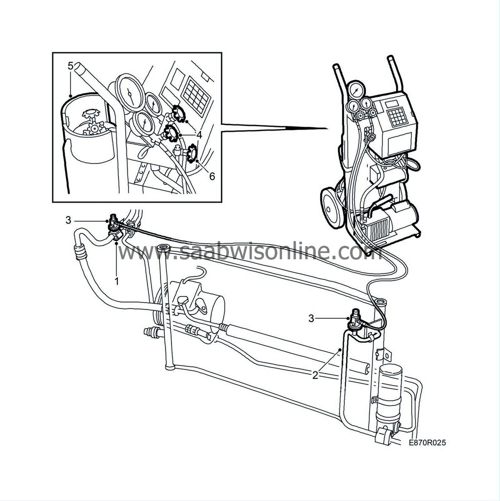
Measuring pressure with the Robinair 1032 Smart Cart
|

|
1.
|
Check that both the valve on the blue low-pressure hose and the valve on the red high-pressure hose on the pressure gauge stand are closed.
|
|
2.
|
Using a snap-on coupling, connect the blue low-pressure hose to the low-pressure side of the A/C system.
|
|
3.
|
Using a snap-on coupling, connect the red high-pressure hose to the high-pressure side of the A/C system.
|
|
4.
|
Open the valves on both snap-on couplings by screwing in the knobs.
|
|
5.
|
Start the engine.
With the engine running at idling speed and the air temperature at 20 °C, the following pressures should be shown on the pressure gauge stand when the compressor is running:
Low pressure side: 1.5-2.5 bar
|
|
Robinair 10324 Smart Cart and Robinair 17234 draining station
|

|
1.
|
Using a snap-on coupling, connect the blue low-pressure hose to the low-pressure side of the A/C system.
|
|
2.
|
Using a snap-on coupling, connect the red high-pressure hose to the high-pressure side of the A/C system.
|
|
3.
|
Open the valves on both snap-on couplings by screwing in the knobs.
|
|
4.
|
Using the yellow hose, connect the pressure gauge stand middle outlet to the draining station.
|
|
5.
|
Open the valves on the blue low-pressure hose and the red high-pressure hose as well as the valve on the yellow hose connected to the pressure gauge stand middle outlet.
|
|
6.
|
Open the blue valve (”Liquid”) for liquid refrigerant and the red valve (”Gas”) for gaseous refrigerant on the draining station container.
|
|
7.
|
Start the draining station. When draining is finished, the draining station will switch off automatically.
|
|
8.
|
Close the valves on the blue low-pressure hose, the red high-pressure hose and the yellow hose connected to the pressure gauge stand middle outlet.
|
|
9.
|
Remove the yellow hose from the draining station. Draining has now been completed and work on the A/C system can commence.
|
|
Vacuum pumping and filling of refrigerant
|

Adjust the amount of compressor oil in the A/C system before commencing vacuum pumping and filling of refrigerant, see
 .
.
|
Important
|
|
Vacuum pumping should be done on simultaneously on both the high pressure and low pressure sides. A non-return valve on the compressor low pressure side makes it impossible to vacuum pump from only one side.
|
|
|
|
1.
|
Using a snap-on coupling, connect the blue low-pressure hose to the low-pressure side of the A/C system.
|
|
2.
|
Using a snap-on coupling, connect the red high-pressure hose to the high-pressure side of the A/C system.
|
|
3.
|
Open the valves on both snap-on couplings by screwing in the knobs.
|
|
4.
|
Open the valves on the blue low-pressure hose and red high-pressure hose on the pressure gauge stand.
|
|
5.
|
Open the blue valve (”Liquid”) for liquid refrigerant on the Smart Cart container.
|
|
6.
|
Check that the valve on the yellow hose on the pressure gauge stand middle outlet is closed.
|
|
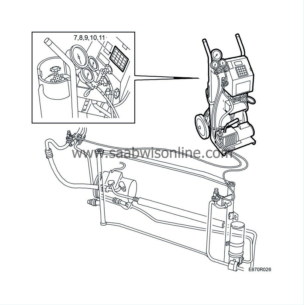
7.
|
Programme 30 minutes vacuum pumping by pressing ”30” on the control panel in position ”Vacuum minus”.

Confirm the selection by pressing ”ENTER”.
|
|
9.
|
Press ”0.87” to indicate the amount of refrigerant (in kilograms) to be refilled.
Confirm the selection by pressing ”ENTER”.
|
|
11.
|
Press ”START” to start vacuum pumping.
|
|
12.
|
Move the A/C hoses slightly and make sure that there are no leaks in the system.
The pressure must not increase by more than 10 mbar over a period of 2 minutes.
|
|
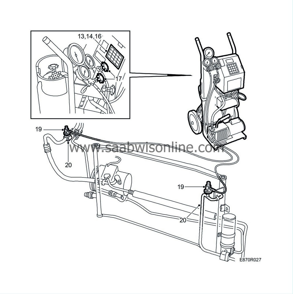
13.
|
Press ”START” to start refilling the refrigerant.

|
|
14.
|
Stop refilling by pressing ”HOLD” when about 200 grams of refrigerant has been refilled.
|
|
15.
|
Move the A/C hoses slightly and check with a leakage detector designed for R134a that the system does not leak.
|
|
16.
|
Continue refilling by pressing ”START”.
”CPL” is shown on the control panel display.
|
|
17.
|
Close the valves for the blue low-pressure hose and the red high-pressure hose on the pressure gauge stand.
|
|
18.
|
Start the car and read the pressure once it has stabilized.
The pressure on the low-pressure side should be 1.5-2.5 bar.
|
|
19.
|
Close the valves on the snap-on couplings on the A/C system service connections by turning the knobs counter-clockwise.
|
|
20.
|
Remove the snap-on couplings and refit the protective plugs in the service valves.
|


 .
.


 Warning

