Gear lever
| Gear lever |
| To remove |
| 1. |
Remove the gear lever housing as described in
 .
.

|
|
| 2. |
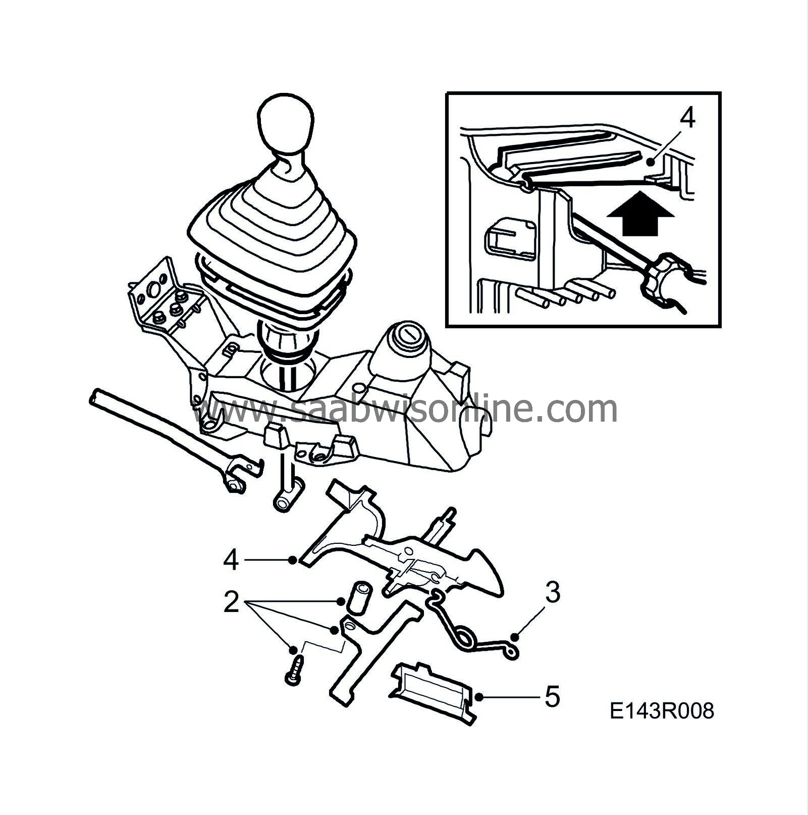
Remove the lock plate holder.
|
|
| 3. |
Remove the spring securing the lock plate.
|
|
| 4. |
Use a screwdriver to disengage the pawl which is controlled from the ignition switch. Lift up the lock plate together with its plastic bracket.
|
|
| 5. |
Remove the deflection limiter.
|
|
| 6. |
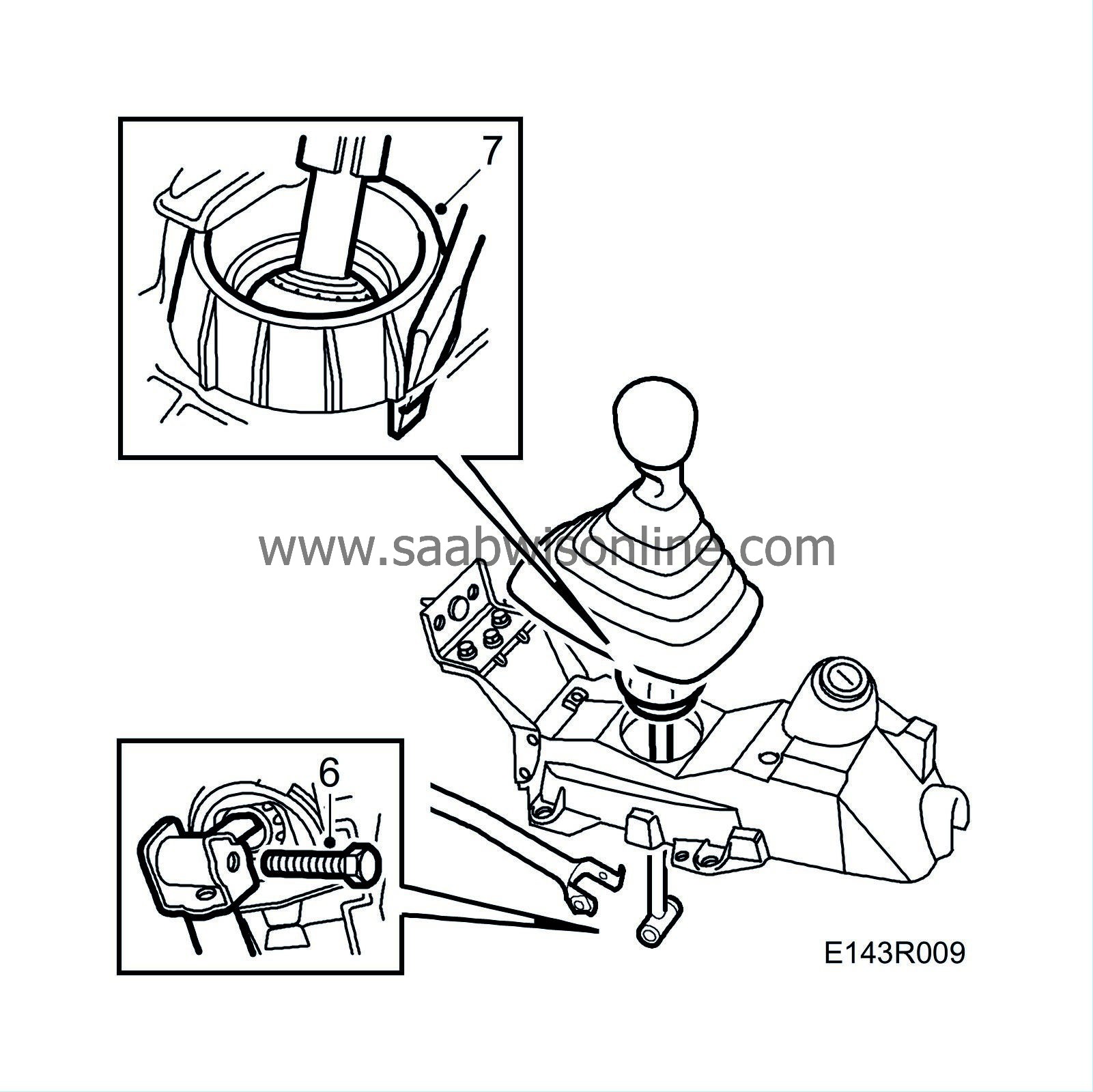
Set the gear lever to reverse and undo the screw securing the selector rod to the gear lever.

|
|
| 7. |
Remove the gear lever and ball socket by
carefully
pressing in the three tabs on the socket using a screwdriver.
|
|
| To fit |

| 1. |
Insert the gear lever and ball socket in the gear lever housing. The O-ring should be between the ball socket and the housing.
|
|
| 2. |
Insert the screw securing the selector rod to the gear lever.
Tightening torque: 20 Nm (15 lbf ft). |
|
| 3. |
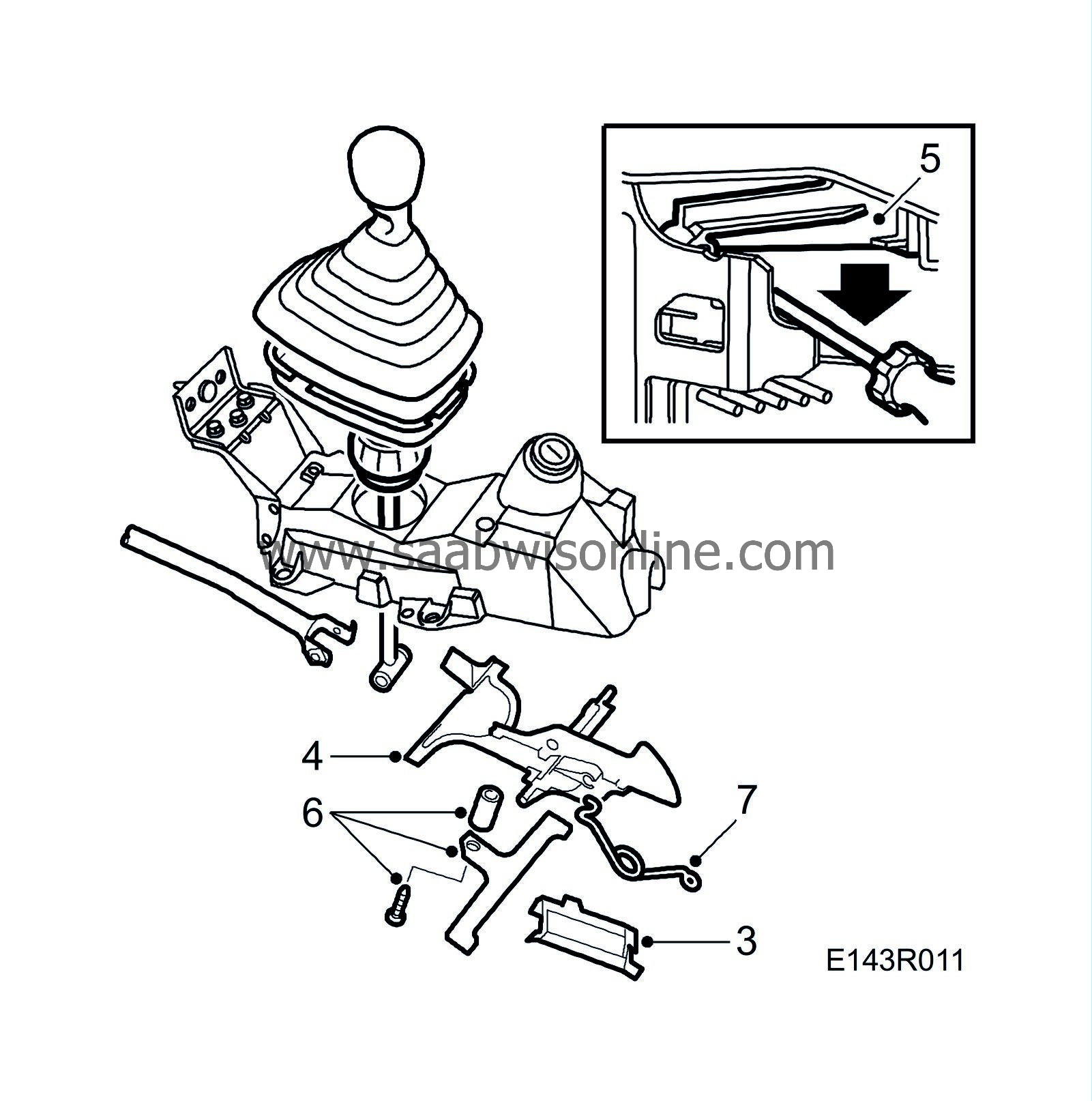
Insert the deflection limiter.

|
|
| 4. |
Insert the lock plate. Check that the lock plate's 2 bearings (rubber bush and dome) in the housing are in place.
|
|
| 5. |
Snap the ignition switch pawl into the lock plate.
|
|
| 6. |
Put the lock plate bracket in place. Apply Loctite 242, part no. 74 96 268, to the bolts holding the lock plate bracket.
|
|
| 7. |
Fit the lock plate spring.
|
|
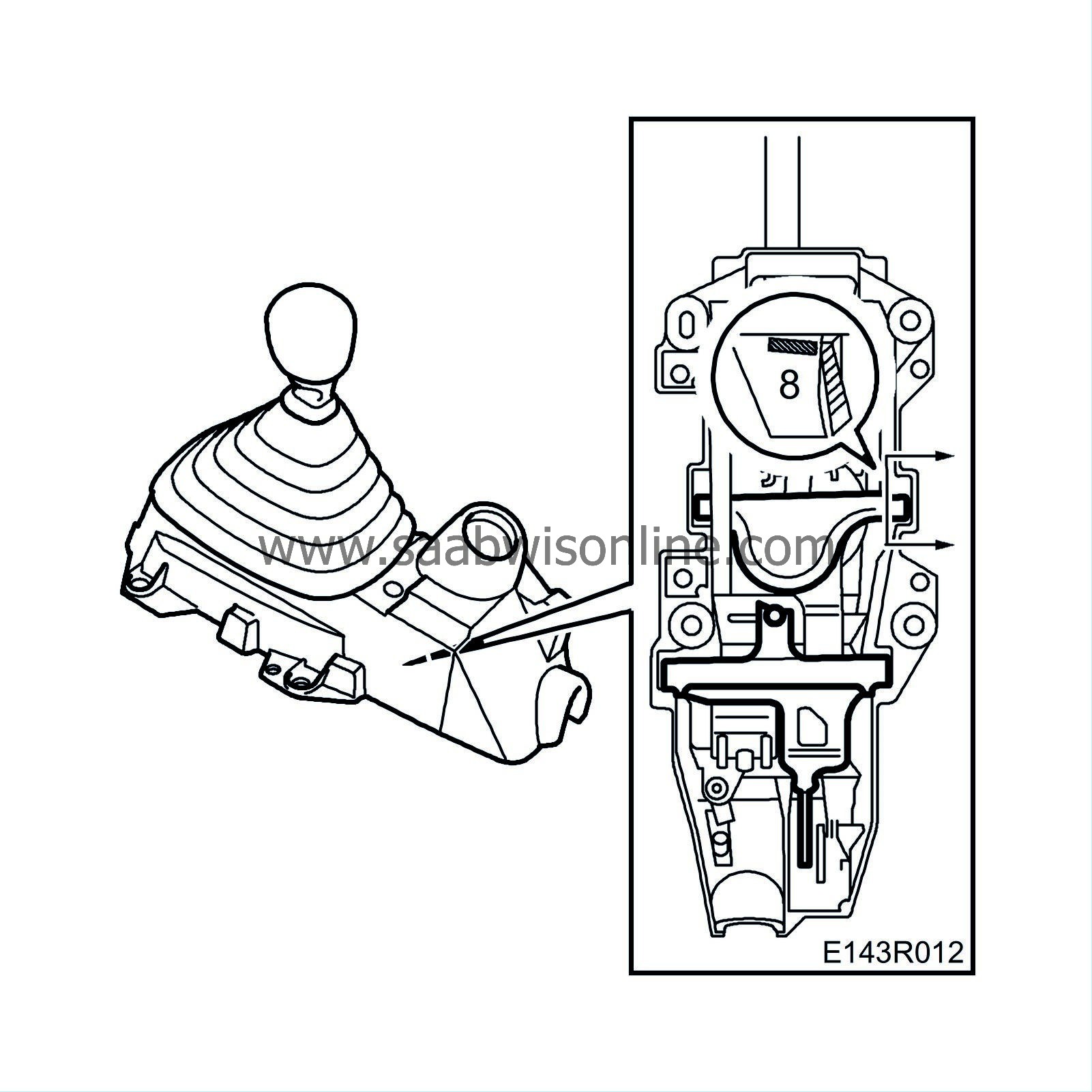
| 9. |
Fit the complete gear lever housing and selector rod as described in
 .
.
|
|


