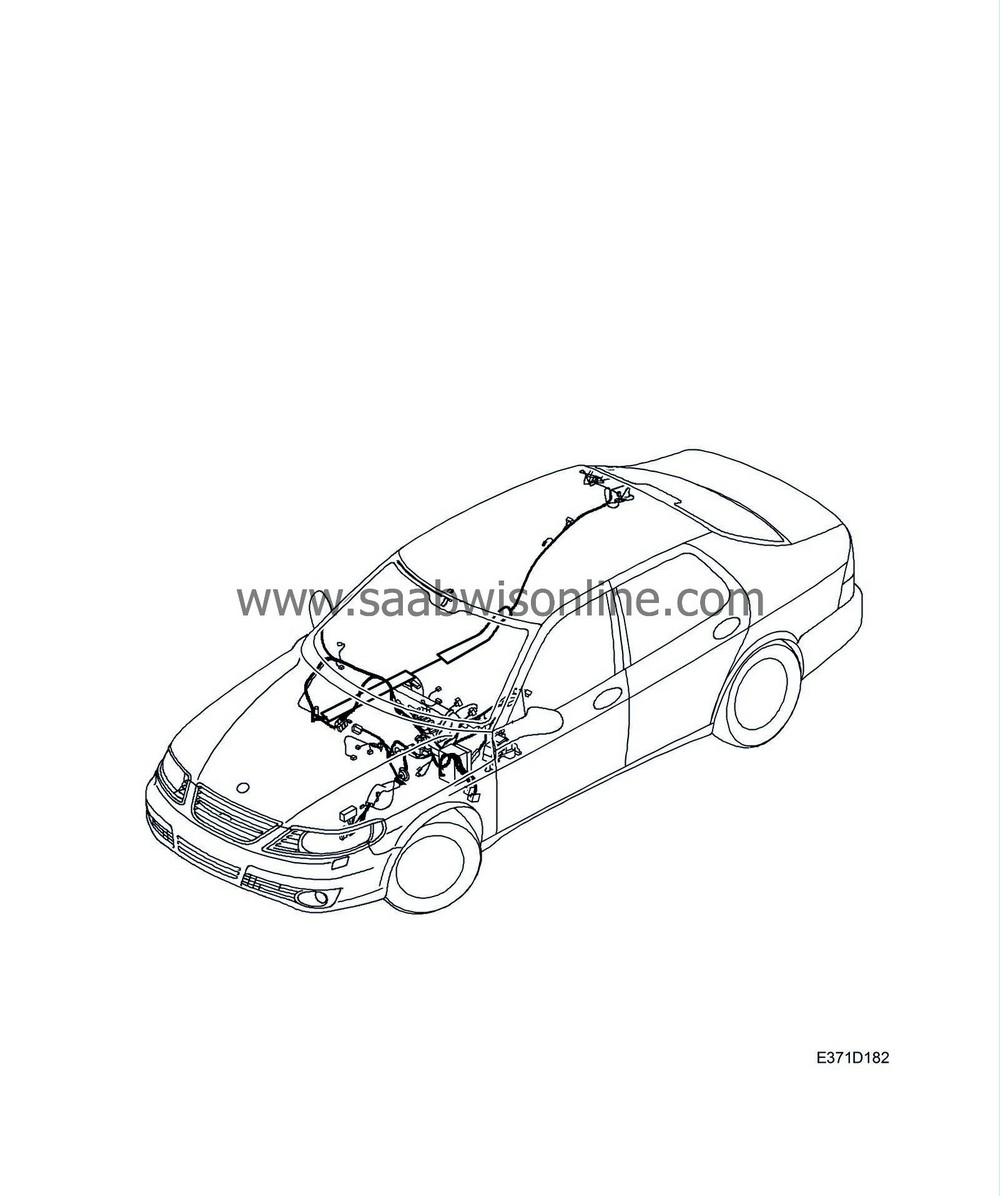
Wiring harness, dashboard
|
|
Wiring harness, dashboard
|
|
Important
|
|
Take care when releasing the locking mechanism on the connector so as not to damage the connector. Pull the halves straight apart to avoid bending the pins. For further information regarding connectors, refer to
Connectors, handling and inspection
.
|
|
|
|
Note
|
|
If the car has a non-Saab radio, check that the customer has the radio code before commencing work.
|
|
3.
|
Remove the fuse box 342a:
|
|
|
•
|
Remove the nuts (A).

|
|
|
•
|
Remove the cable tie (B).
|
|
4.
|
Remove the clip (C) from the coolant reservoir.
|
|
5.
|
Remove the connector (D) from the level sensor.
|
|
6.
|
Disconnect the cable duct (A).

|
|
7.
|
Disconnect the fuse holder (B) to the positive feed.
|
|
8.
|
Remove the connectors (C) to the wiring harness, engine.
|
|
9.
|
Remove the connector (D) from the holder.
|
|
10.
|
Remove the grounding points (E).
|
|
12.
|
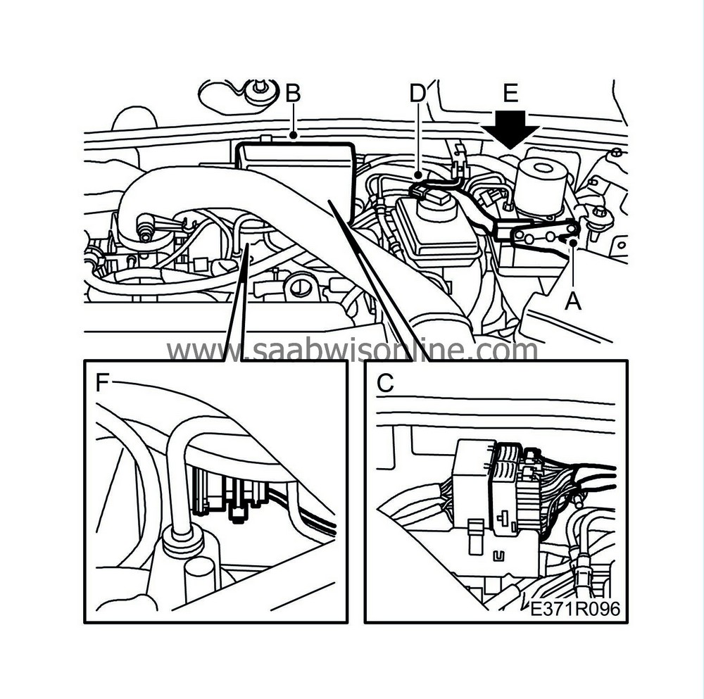
Remove the connector (A) from the ABS unit.
|
|
13.
|
Remove the cover (B) and disconnect the connector (C) at the bulkhead partition.
|
|
14.
|
Remove the connector (D) from the level sensor.
|
|
15.
|
Remove the fixing (E) at the bulkhead partition.
|
|
16.
|
Remove the cable tie (F) around the connector.
|
|
17.
|
Remove the connector for the wiper motor:
|
|
|
•
|
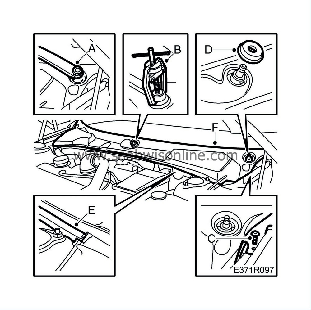
Where appropriate, remove covers from the wiper arm retaining nuts
|
|
|
•
|
Remove the protective cover retaining screws (C) and the rubber seals from the wiper spindles (D).
|
|
|
•
|
Loosen the rubber moulding (E) from the bulkhead partition, but let it rest on the wings.
|
|
|
•
|
Lift off the protective cover (F) over the bulkhead partition space.
|
|
|
•
|
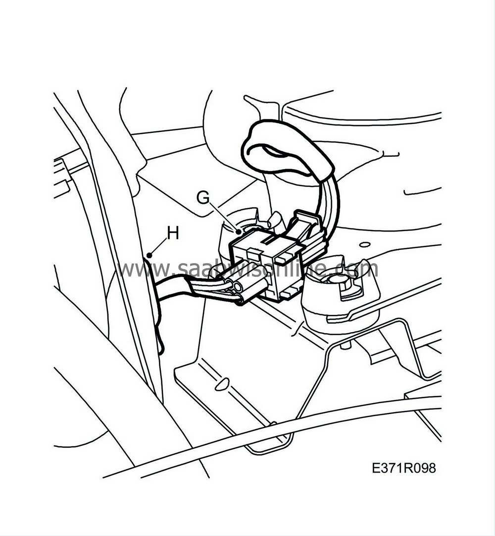
Disconnect the connector (G) to the wiper motor.
|
|
|
•
|
Remove the rubber grommet (H).
|
|
24.
|
Remove the wiring harness from the cabin roof and right A-pillar:
 Warning
|
|
Take care not to damage or loosen the energy absorbers. Damaged or loose energy absorbers must not be refitted. If the occasion should arise, the entire headlining must be changed. Damaged energy absorbers may impair head protection in case of a collision.
|
|
|
|
|
|
|
|
|
•
|
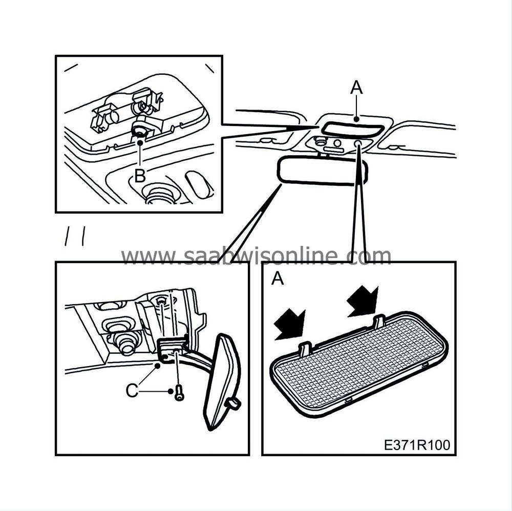
Remove the lock cover glass (A) by carefully bending the front edge with a chisel in the lighting glass clip socket.
|
|
|
•
|
Remove the lock cover screw (B). Undo the connectors and lift down the lock cover.
|
|
|
•
|
Remove the interior rearview mirror (C).
|
|
|
•
|
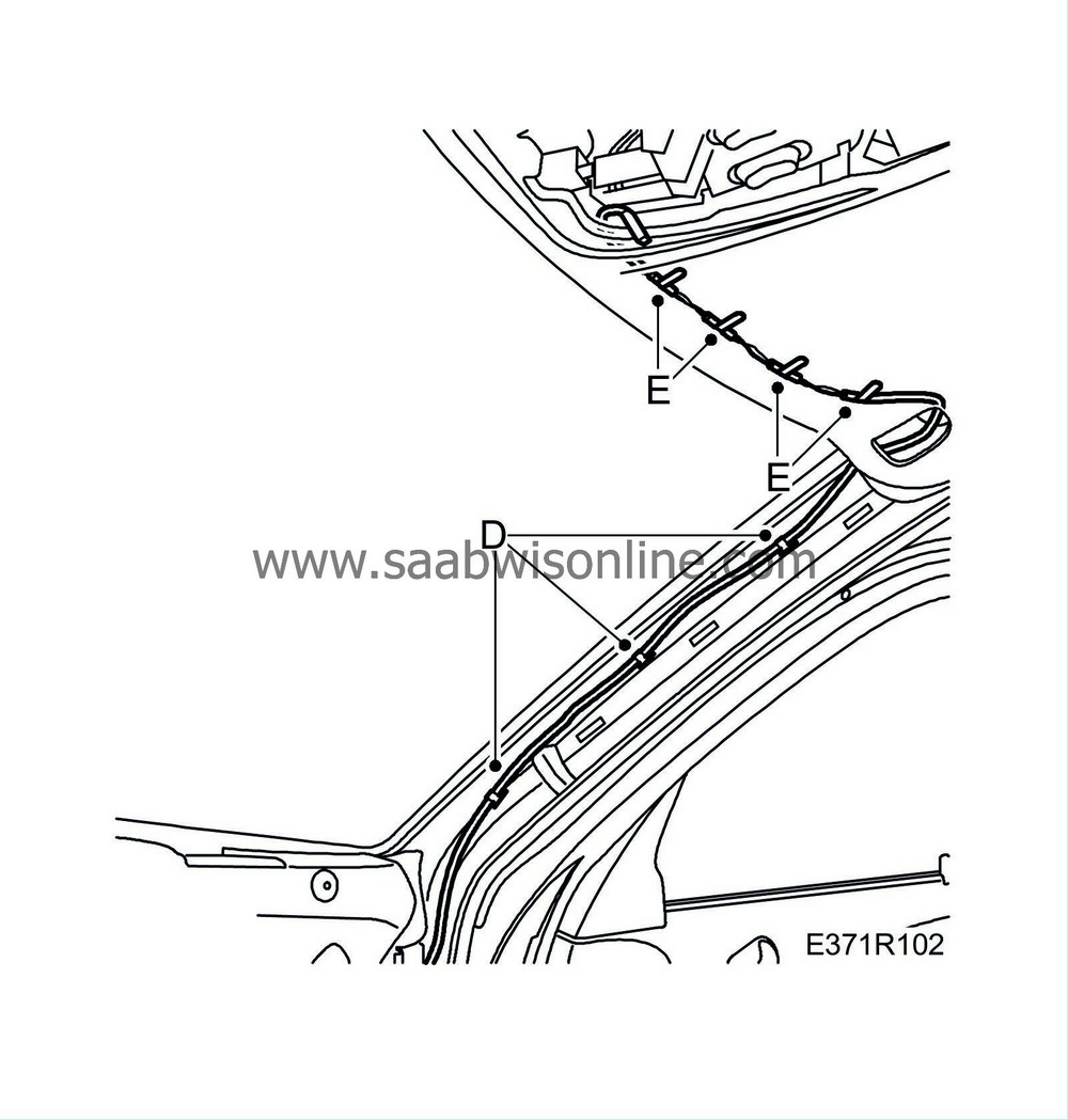
Remove the wiring harness clips (D, E).
|
|
25.
|
Remove the wiring harness from the driver's side:
|
|
|
•
|
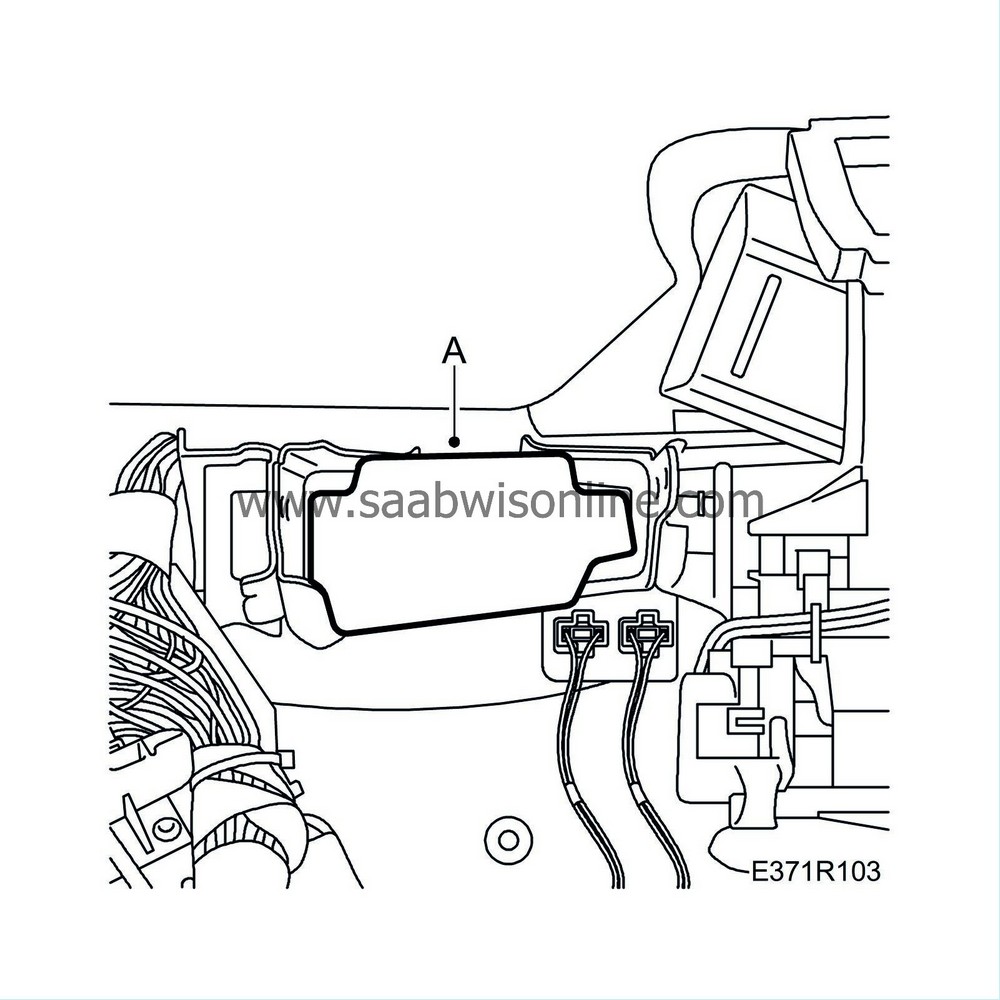
Remove the foam block (A) from the steering column assembly bracket.
|
|
|
•
|
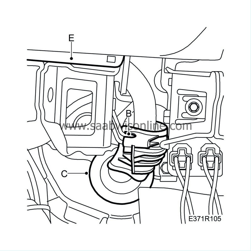
Remove the screw (B) to the wiring harness control.
|
|
|
•
|
Remove the rubber bellows (C) and insert the wiring harness from the engine bay to the cabin.
|
|
|
•
|
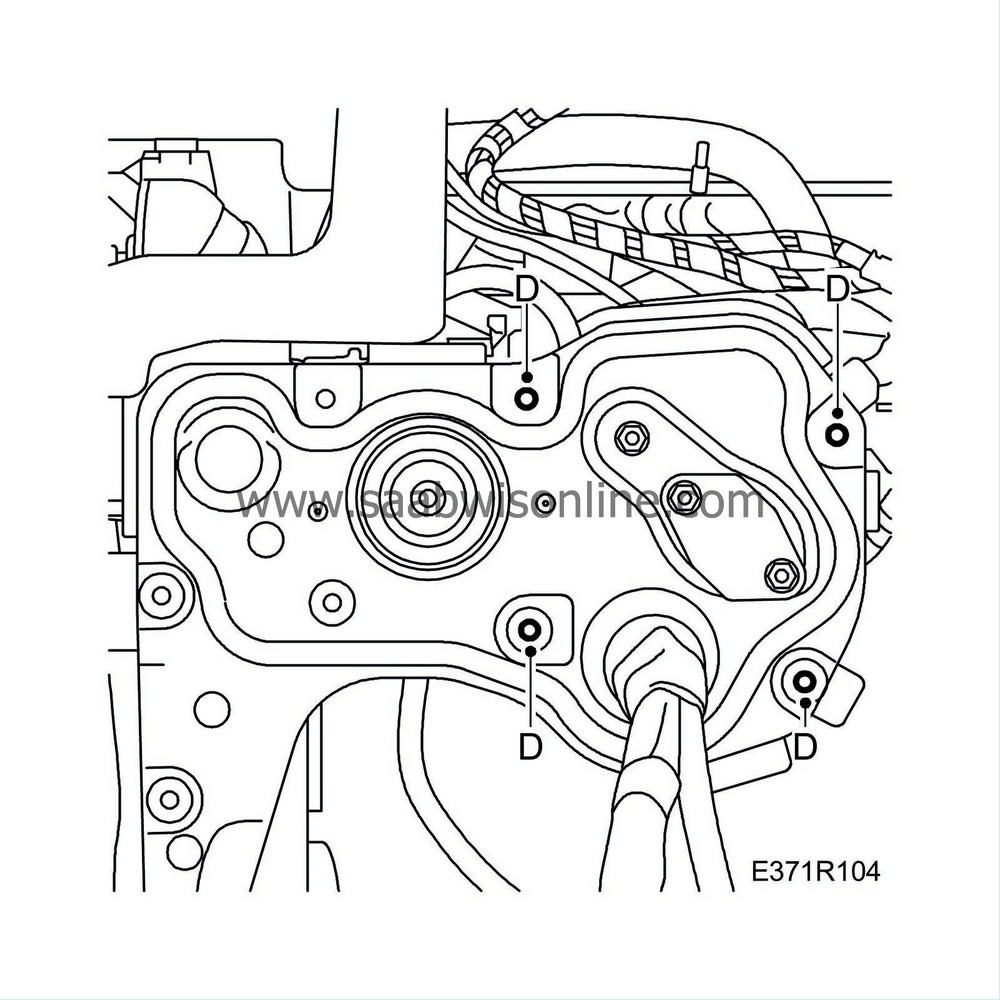
Undo the nuts (D) for the bulkhead partition plate, from the engine bay, until the plastic duct above the steering column assembly can be removed.
|
|
|
•
|
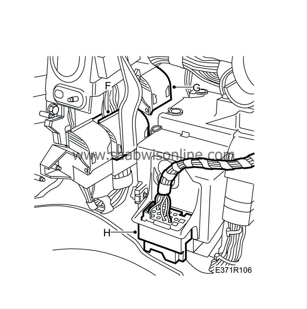
Remove the plastic duct (E) above the steering column assembly bracket. Use a screwdriver, bend out the lock lugs and pull the duct back until it is released.
|
|
|
•
|
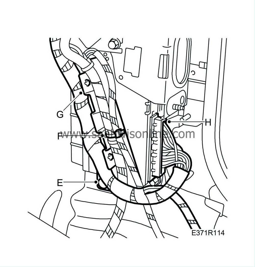
Remove the connectors (F, G, H).
|
|
|
•
|
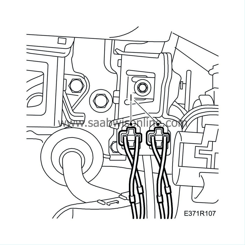
Remove the connectors (I) for the pedal contacts.
|
|
26.
|
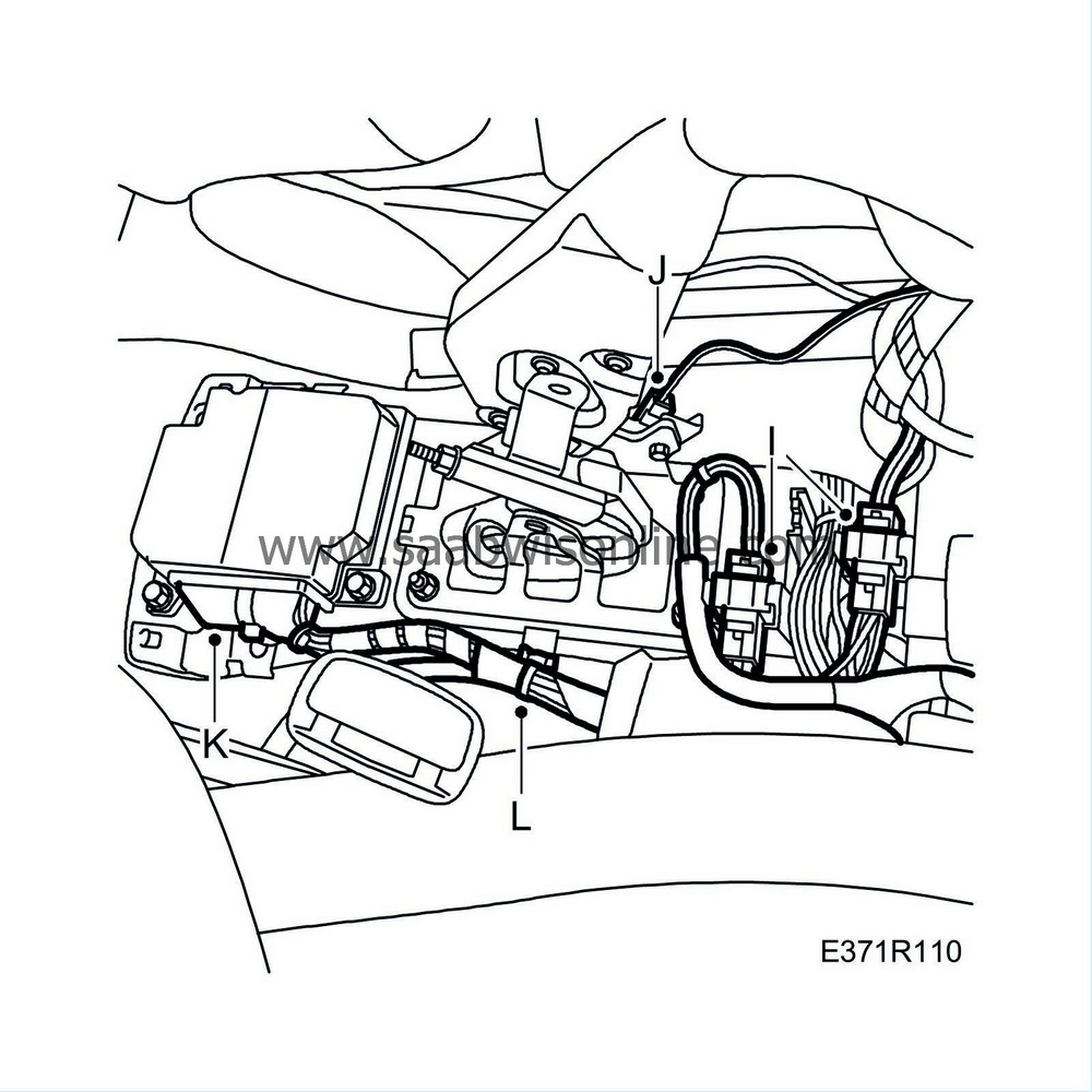
Remove the wiring harness from the centre console.
|
|
|
•
|
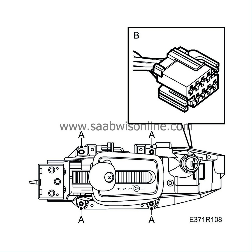
Remove the gear lever housing (A).
|
|
|
•
|
Remove the connector (B) from the ignition barrel.
|
|
|
•
|
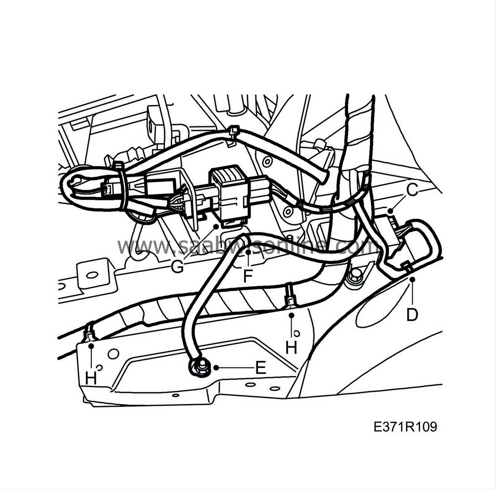
Remove the connector (C) from the yaw angle sensor.
|
|
|
•
|
Remove the grounding points (E) and the clip (F).
|
|
|
•
|
Remove the connector (G) from the gear lever housing bracket.
|
|
|
•
|
Carefully cut the floor mat behind the gear lever housing.
|
|
|
•
|
Remove the connectors (I).
|
|
|
•
|
Remove the connector (J) from the handbrake sensor.
|
|
|
•
|
Remove the connector (K) from the airbag electronic unit and the clip (L).
|
|
27.
|
Remove the wiring harness from the passenger side.
|
|
|
•
|
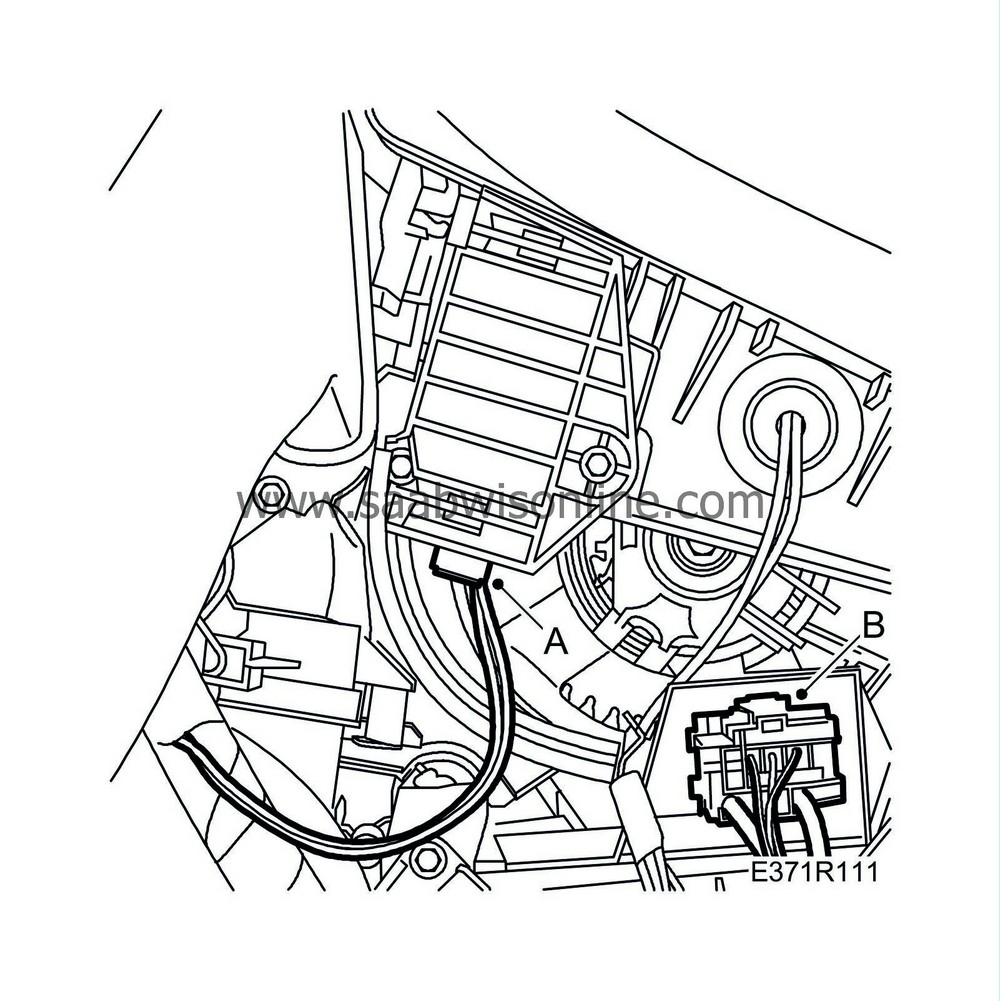
Remove the connector (A) from the recirculation motor.
|
|
|
•
|
Remove the connector (B) from the heating and ventilation unit.
|
|
|
•
|
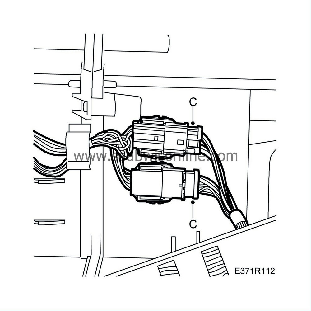
Remove the connectors (C) from the heat system wiring harness.
|
|
|
•
|
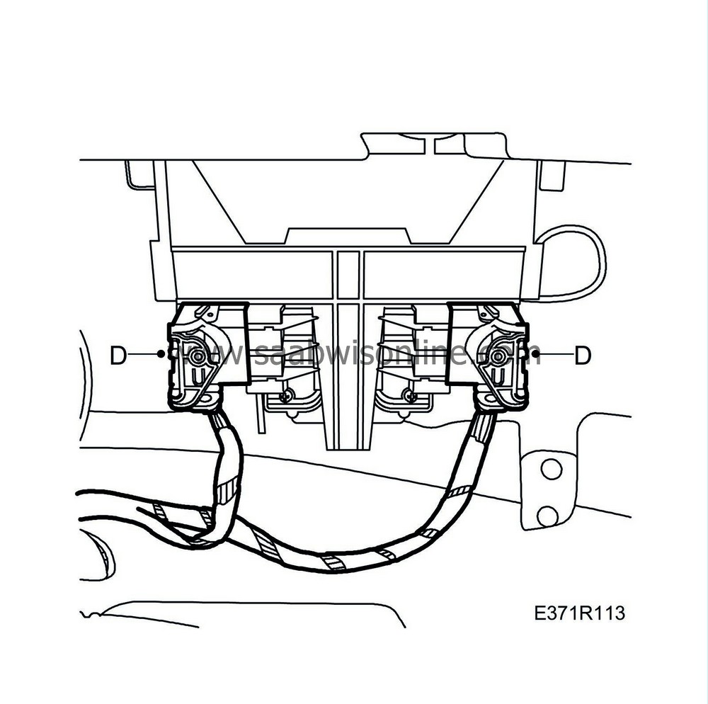
Remove the connectors (D) from the automatic transmission control module.
|
|
|
•
|
Remove the two-stage rivet (E) from the cable duct.
|
|
|
•
|
Remove the clip (F) from the cable duct.
|
|
|
•
|
Remove the cable duct (G).
|
|
|
•
|
Remove the connector (H) from the amplifier.
|
|
28.
|
Remove the wiring harness from the right side:
|
|
|
•
|
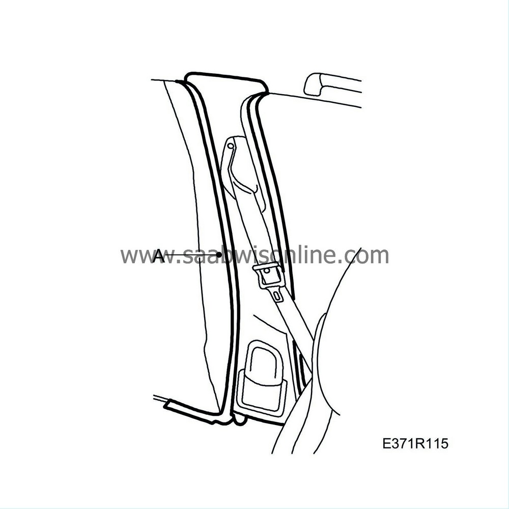
Undo the B-pillar trim (A) so that the air duct is disconnected.
|
|
|
•
|
Fold up the rear seat right seat cushion and fold down the backrest.
|
|
|
•
|
Fold back the mat from the right rear door seal.
|
|
29.
|
Remove the rear section of the wiring harness:
 Warning
|
|
Take care not to damage or loosen the energy absorbers. Damaged or loose energy absorbers must not be refitted. If the occasion should arise, the entire headlining must be changed. Damaged energy absorbers may impair head protection in case of a collision.
|
|
|
|
|
|
|
|
|
•
|
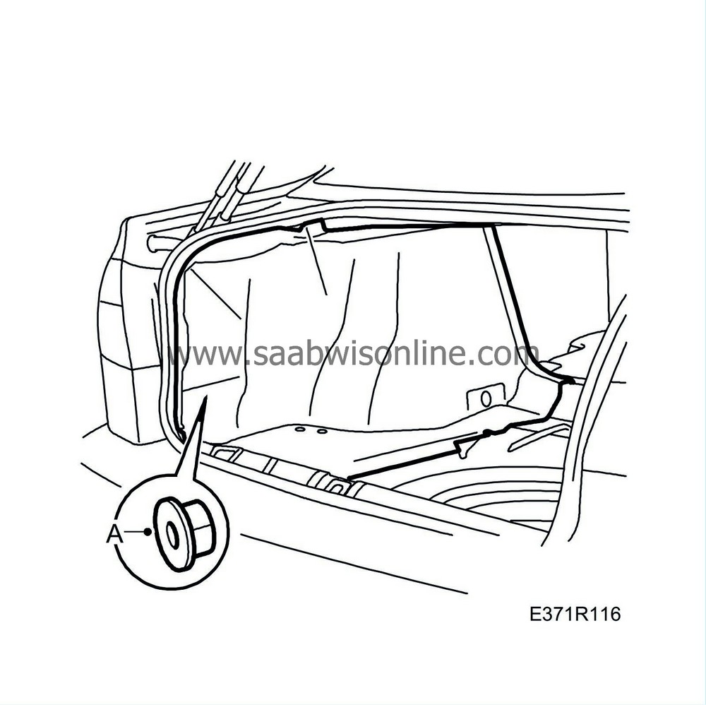
Undo the right luggage compartment trim, 3x nut (A).
|
|
|
•
|
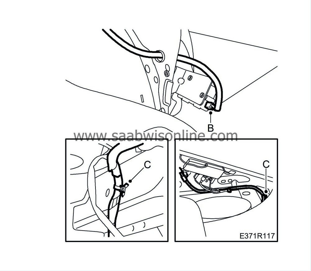
Remove the connector (B) for the fuel filler flap lock and pull the cable out through the hole.
|
|
|
•
|
Remove the wiring harness clip (C) in the luggage compartment/parcel shelf.
|
|
|
•
|
Remove the rear right neck support and fold down other rear neck supports.
|
|
|
•
|
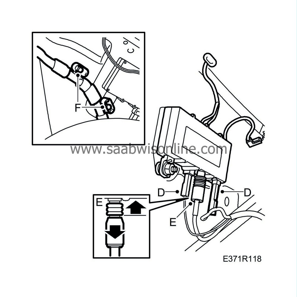
Remove the connectors (D) and antenna cable (E) for the antenna amplifier and fixings (F).
|
|
|
•
|
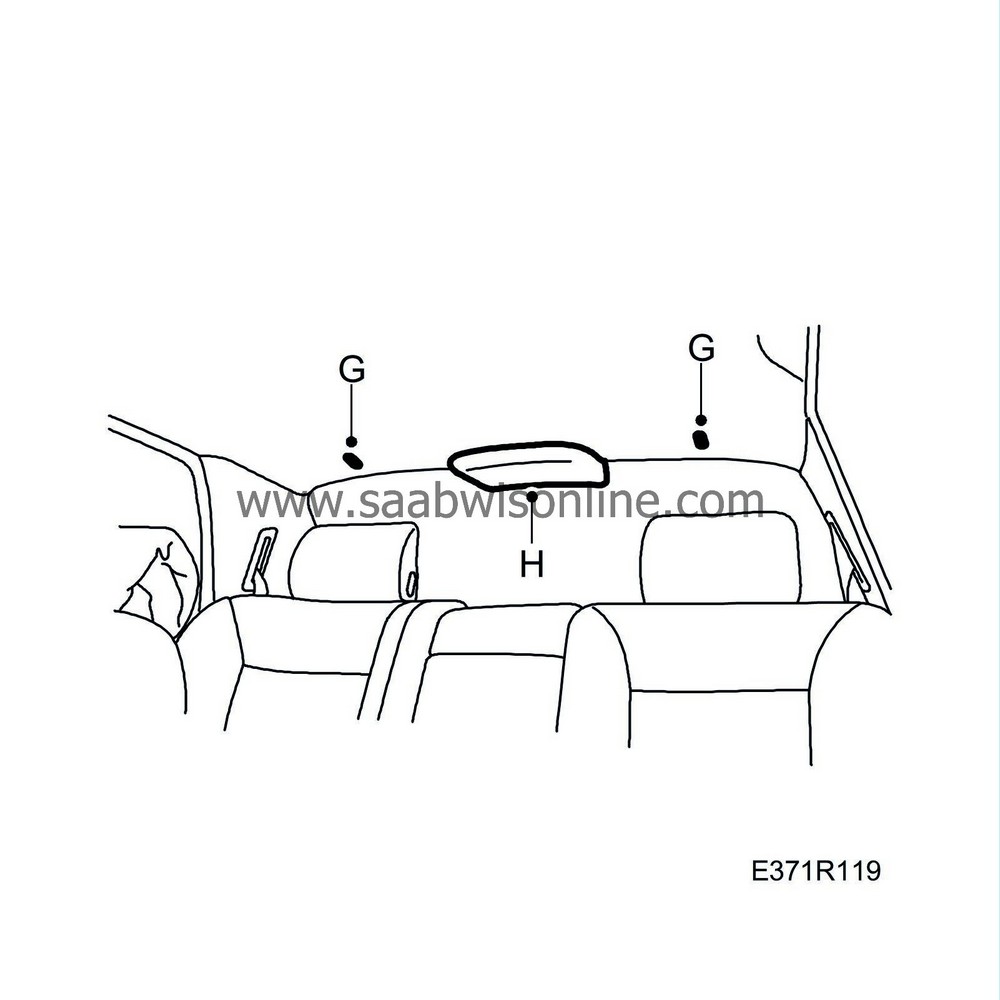
Remove the clips (G) which hold the headlining at the rear edge by turning them through 90 degrees.
|
|
|
•
|
Remove the cover (H) for the high level brake light.
|
|
|
•
|
Fold down the roof until it is possible to access the wiring harness.
|
|
|
•
|
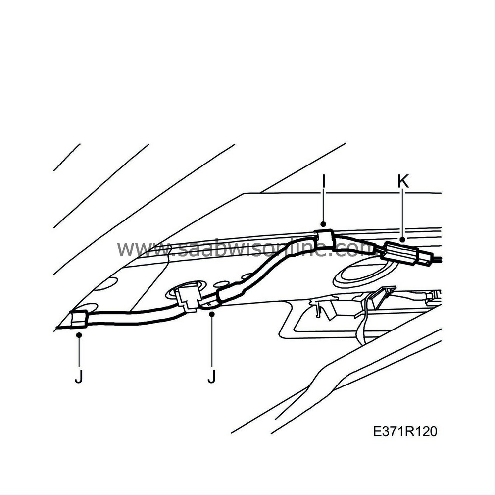
Remove the wiring harness fixing (I) and clips (J) at the rear edge of the roof.
|
|
|
•
|
Remove the connector (K) for the roof antenna.
|
|
|
•
|
Pull the wiring harness down through the hole in the parcel shelf to the luggage compartment.
|
|
|
•
|
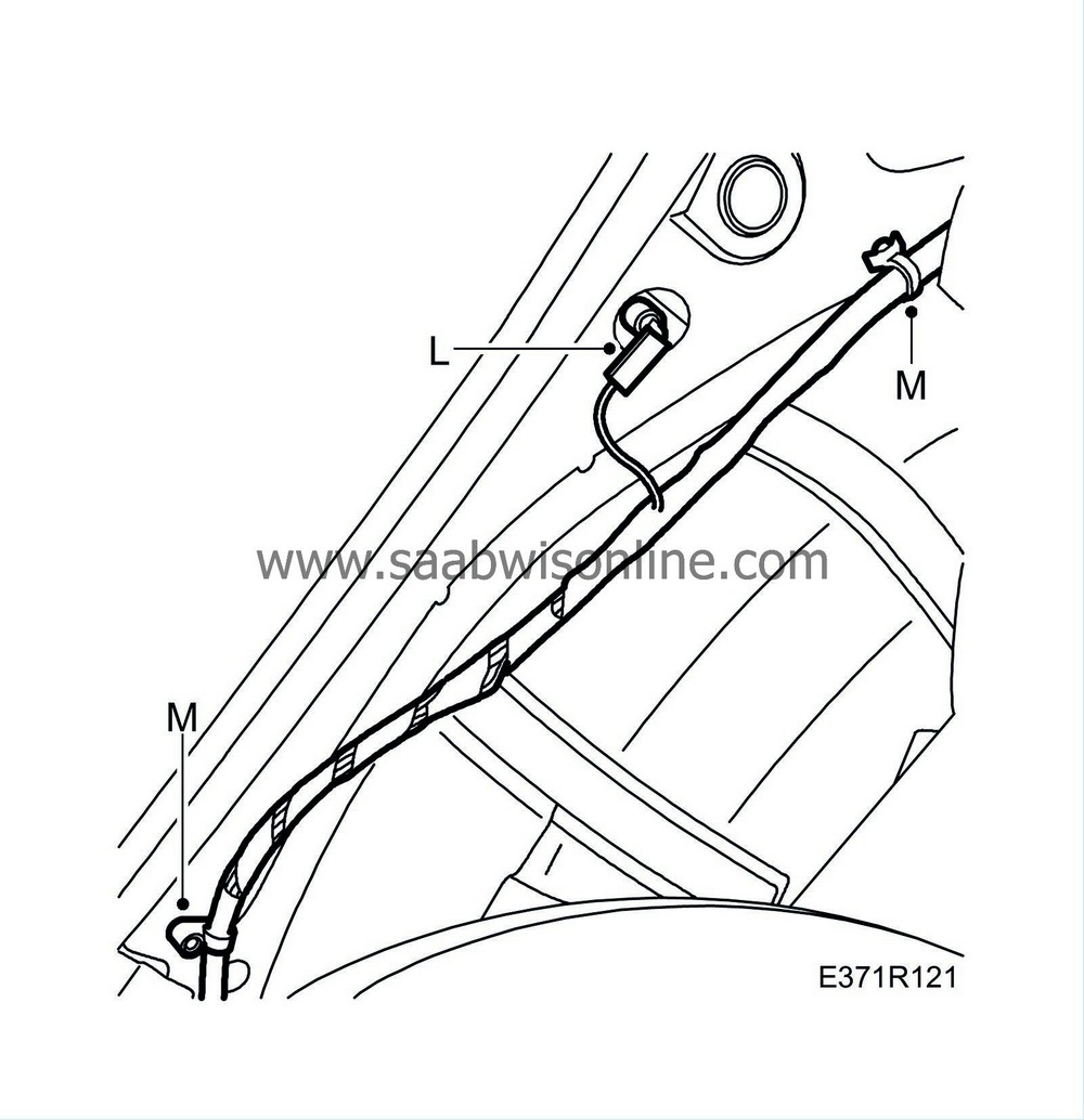
Remove the connector (L) from the door switch.
|
|
|
•
|
Undo the clips (M), front of wheel housing.
|
|
|
•
|
Pull the wiring harness forwards from the luggage compartment to the right rear door opening.
|
|
|
•
|
Undo the rear cable duct.
|
|
|
•
|
Pull the wiring harness forward to the right front door.
|
|
|
•
|
Undo the front cable duct.
|
|
|
•
|
Remove the wiring harness through the right front door.
|
 Warning
|
|
The cable harness must be routed and secured so that it cannot be pinched or chafe against anything when removed components are reinstalled. Incorrect routing could lead to wiring harness damage and cause short-circuit or fire.
|
|
|
|
|
|
|
Important
|
|
Take care when plugging in the connector so as not to damage or press out the pins/sleeves in the connector. For further information regarding connectors, refer to
Connectors, handling and inspection
.
|
|
|
|
Note
|
|
Route the new wiring harness in the same way as the old one and secure it in the same way. Make sure all grommets seal tightly.
|
|
Spray all connectors with contact spray in order to prevent verdigris formation, and clean and coat all grounding points with Vaseline.
|
|
Plug in the connectors to their respective components. If in doubt refer to wiring diagrams/component lists for the respective system.
|
|
1.
|
Position the wiring harness in the front part of the cabin.
|
|
2.
|
Fit the wiring harness to the right side:
 Warning
|
|
Take care not to damage or loosen the energy absorbers. Damaged or loose energy absorbers must not be refitted. If the occasion should arise, the entire headlining must be changed. Damaged energy absorbers may impair head protection in case of a collision.
|
|
|
|
|
|
|
|
|
•
|
Fit the front cable duct to the right sill.
|
|
|
•
|
Position the wiring harness past and behind the air duct on the right B-pillar.
|
|
|
•
|
Fit the rear cable duct to the right sill.
|
|
|
•
|
Pull the wiring harness to the luggage compartment through the hole beneath the parcel shelf.
|
|
|
•
|
Fit the clips (M) at the front of the wheel housing.

|
|
|
•
|
Plug in the connector (L) to the door switch.
|
|
3.
|
Fit the rear section of the wiring harness:
 Warning
|
|
Take care not to damage or loosen the energy absorbers. Damaged or loose energy absorbers must not be refitted. If the occasion should arise, the entire headlining must be changed. Damaged energy absorbers may impair head protection in case of a collision.
|
|
|
|
|
|
|
|
|
•
|
Pull the cable through the hole and connect the connector (B) to the fuel filler flap lock.

|
|
|
•
|
Pull the wiring harness to the parcel shelf through the hole in the luggage compartment.
|
|
|
•
|
Fit the wiring harness clip (C) in the luggage compartment/parcel shelf.
|
|
|
•
|
Fit the luggage compartment trim, 3x nut (A).

|
|
|
•
|
Plug in the connectors (D, E) to the antenna amplifier and fixings (F).

|
|
|
•
|
Fit the wiring harness fixing (I) and clips (J) at the rear edge of the roof.

|
|
|
•
|
Plug in the connector (K) for the roof antenna.
|
|
|
•
|
Move up the headlining and fit the clips (G) by turning them through 90 degrees.

|
|
|
•
|
Fit the cover (H) for the high level brake light.
|
|
|
•
|
Fit the rear right neck support and fold up the other neck supports.
|
|
|
•
|
Fold the mat back into place beneath the door seal.
|
|
|
•
|
Raise the rear backrest and fold down the seat cushion.
|
|
4.
|
Fit the wiring harness to the passenger side:
|
|
|
•
|
Plug in the connector (H) to the amplifier.

|
|
|
•
|
Fit the wiring harness cable duct (G) in front of the amplifier.
|
|
|
•
|
Fit the two-stage rivet (E) to the cable duct.
|
|
|
•
|
Fit the clip (F) to the cable duct.
|
|
|
•
|
Pull the steering wheel axis under the wiring harness.
|
|
|
•
|
Fit the connectors (D) to the automatic transmission control module.

|
|
|
•
|
Fit the connectors (C) to the heat system wiring harness.

|
|
|
•
|
Plug in the connector (B) to the heating and ventilation unit.

|
|
|
•
|
Plug in the connector (A) to the recirculation motor.
|
|
5.
|
Fit the wiring harness to the driver's side:
|
|
|
•
|
Fit the plastic duct (E) above the steering column assembly bracket.

|
|
|
•
|
Tighten the nuts (D) for the bulkhead partition plate, from the engine bay.
Tightening torque 25 Nm (18 lbf ft)

|
|
|
•
|
Plug in the connectors (I) for the pedal contacts.

|
|
|
•
|
Pass the wiring harness from the cabin to the engine bay and fit the rubber bellows (C).

|
|
|
•
|
Fit the screw (B) to the wiring harness control.
|
|
|
•
|
Fit the foam block (A) to the steering column assembly bracket.

|
|
|
•
|
Plug in the connectors (F, G, H).

|
|
6.
|
Fit the wiring harness to the centre console:
|
|
|
•
|
Plug in the connector (K) to the airbag electronic unit and the clip (L).

|
|
|
•
|
Plug in the connector (J) to the handbrake sensor.
|
|
|
•
|
Plug in the connectors (I).
|
|
|
•
|
Fold down the floor mat.
|
|
|
•
|
Fit the clips (H).

|
|
|
•
|
Fit the connector (G) to the gear lever housing bracket.
|
|
|
•
|
Fit the grounding points (E) and the clip (F).
|
|
|
•
|
Plug in the connector (C) to the yaw angle sensor.
|
|
|
•
|
Plug in the connector (B) to the ignition barrel.

|
|
|
•
|
Fit the gear lever housing (A).
Tightening torque 8 Nm (6 lbf ft)
|
|
7.
|
Fit the wiring harness to the cabin roof and right A-pillar:
 Warning
|
|
Take care not to damage or loosen the energy absorbers. Damaged or loose energy absorbers must not be refitted. If the occasion should arise, the entire headlining must be changed. Damaged energy absorbers may impair head protection in case of a collision.
|
|
|
|
|
|
|
|
|
•
|
Fit the wiring harness clips (D, E).

|
|
|
•
|
Fit the interior rearview mirror (C).

|
|
|
•
|
Plug in the connector and fit the lock cover screw (B).
|
|
|
•
|
Fit the lock cover glass (A).
|
|
14.
|
Plug in the connector for the wiper motor:
|
|
|
•
|
Fit the rubber grommet (H).

|
|
|
•
|
Plug in the connector (G) to the wiper motor.
|
|
|
•
|
Place the protective cover (F) over the bulkhead partition space.

|
|
|
•
|
Fit the rubber sealing strip (E) to the bulkhead partition.
|
|
|
•
|
Fit the protective cover retaining screws (C) and the rubber seals from the wiper spindles (D).
|
|
|
•
|
Fit the wiper arms (A).
|
|
|
•
|
Where appropriate, fit covers over the wiper arm retaining nuts.
|
|
15.
|
Fit the cable tie (F) around the connector.

|
|
16.
|
Fit the fixing (E) at the bulkhead partition.
|
|
17.
|
Plug in the connector (A) to the ABS unit.
|
|
18.
|
Plug in the connector (D) to the level sensor.
|
|
19.
|
Plug in the connectors (C) at the bulkhead partition and fit the cover (B).
|
|
21.
|
Fit the grounding points (E).

|
|
22.
|
Plug in the connector (D) to the holder.
|
|
23.
|
Plug in the connectors (C) to the wiring harness, engine.
|
|
24.
|
Connect the fuse holder (B) to the positive feed.
|
|
25.
|
Fit the cable duct (A).
|
|
26.
|
Plug in the connector (D) to the level sensor.

|
|
27.
|
Fit the clip (C) to the coolant reservoir.
|
|
28.
|
Fit the fuse box 342a:
|


 Warning

