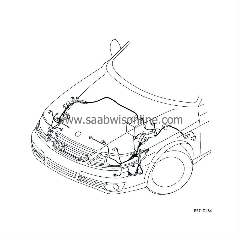
Wiring harness, front
| Wiring harness, front |
| To remove |
| Note | ||
|
If the car is equipped with a radio other than a genuine Saab radio, check that the customer has the radio code before commencing work. |
| 1. |
Remove the
battery shelf
.
|
|
| 2. |
Remove the
sill protector
.
|
|
| 3. |
Remove the wiring harness beneath the instrument panel.
|
|
| • |
Remove the clip (A) and fold back the carpet.

|
| • |
Remove the cover (B).
|
| • |
Remove the data link connector (C).
|
| • |
Remove the connector for the floor lighting.
|
| • |
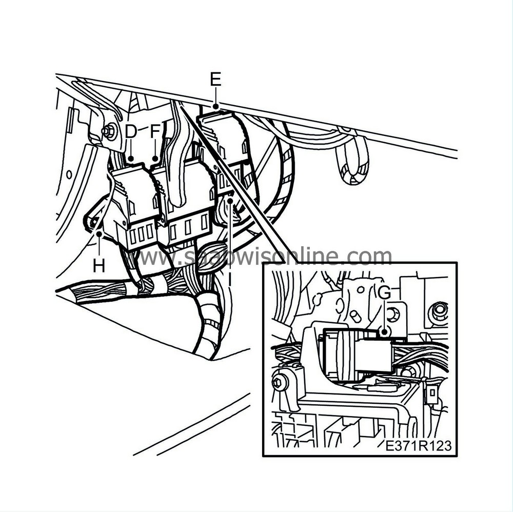
Remove the connectors (D, E, F, G).
|
| • |
Remove the holder (H).
|
| • |
Remove the connector (I) from the holder.
|
| • |
Release the wiring harness.
|
| 4. |
Remove the fuse box 342a:
|
|
| • |
Remove the nuts (A).

|
| • |
Remove the cable tie (B).
|
| 5. |
Remove the clip (C) from the coolant reservoir.
|
|
| 6. |
Remove the connector (D) from the level sensor.
|
|
| 7. |
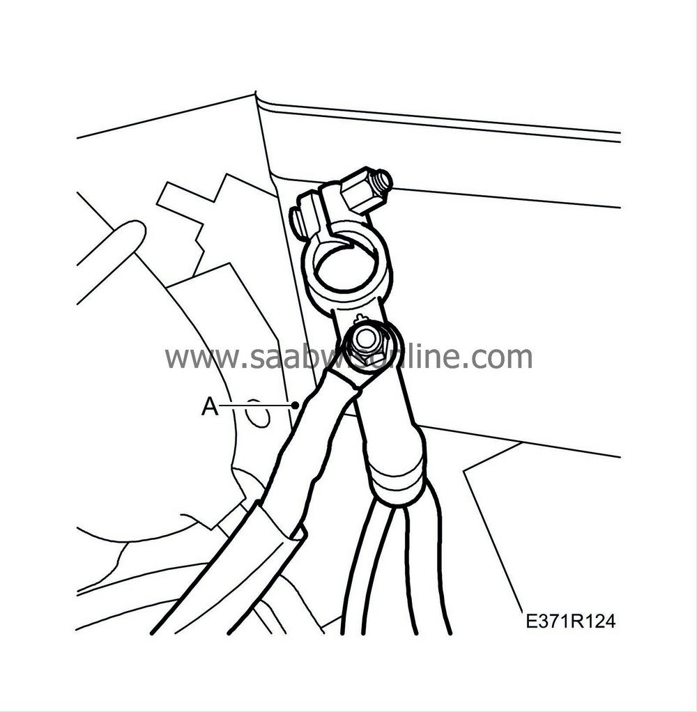
Remove the cable (A) from the battery cable clip to the battery's positive terminal.
|
|
| 8. |
Remove the cable duct:
|
|
| • |
Open the cable duct snap locks and divide the cable duct (A).

|
| • |
Remove the cable duct mountings (B).
|
| 9. |
Remove the wiring harness rubber grommet from the bulkhead partition.
|
|
| 10. |
Remove
bumper shell, front
.
|
|
| 11. |
Remove the siren connector:
|
|
| • |
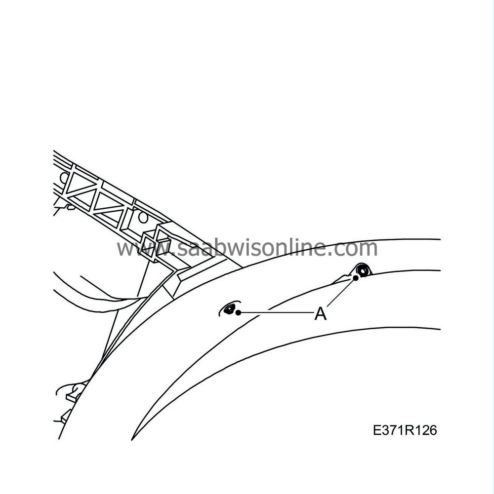
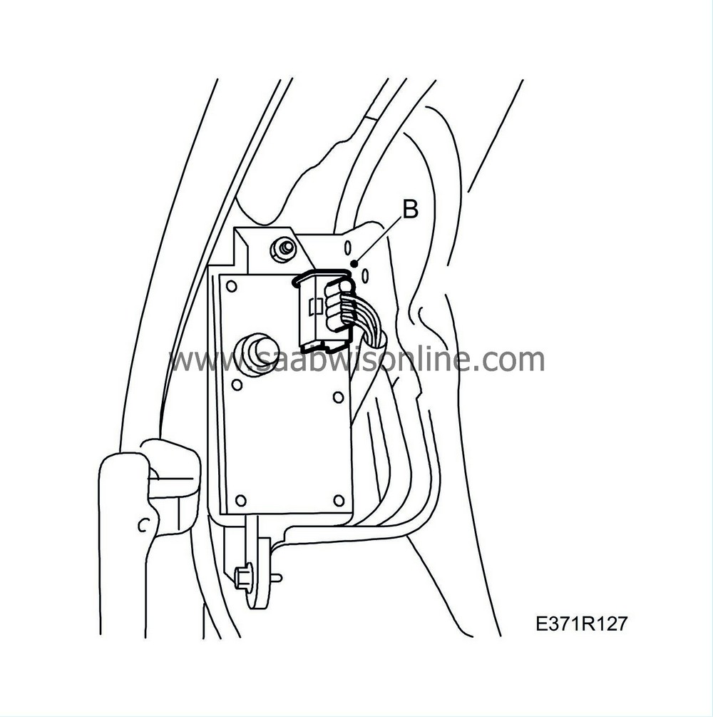
Remove the screws (A) for the wheel arch liner.
|
| • |
Lift out the wheel arch liner and remove the siren connector (B).
|
| 12. |
Remove the connector housings (A) for the washer pumps and washer fluid sensor (B).

|
|
| 13. |
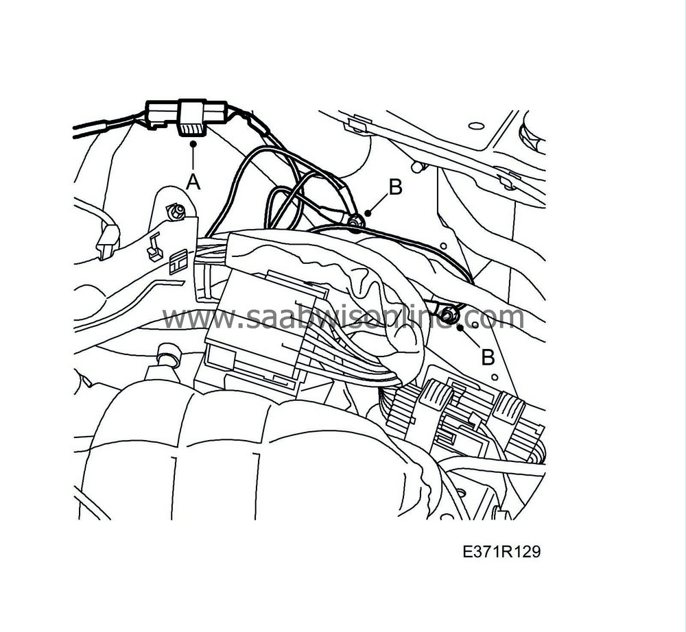
Disconnect the connector (A) to the wheel sensor and remove the grounding points (B).
|
|
| 14. |
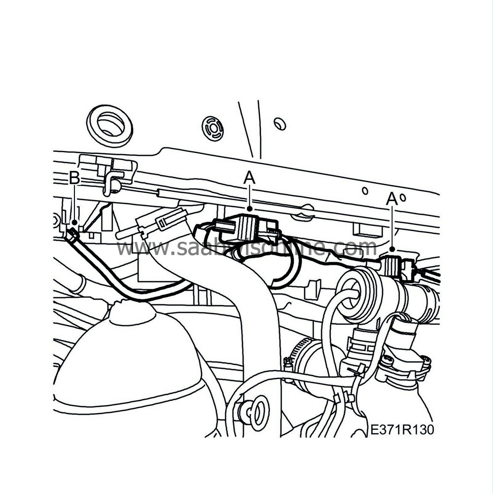
Disconnect the connectors (A) to the radiator fans and remove the cable tie (B).
|
|
| 15. |
Remove the connectors (A) for the headlamps.

|
|
| 16. |
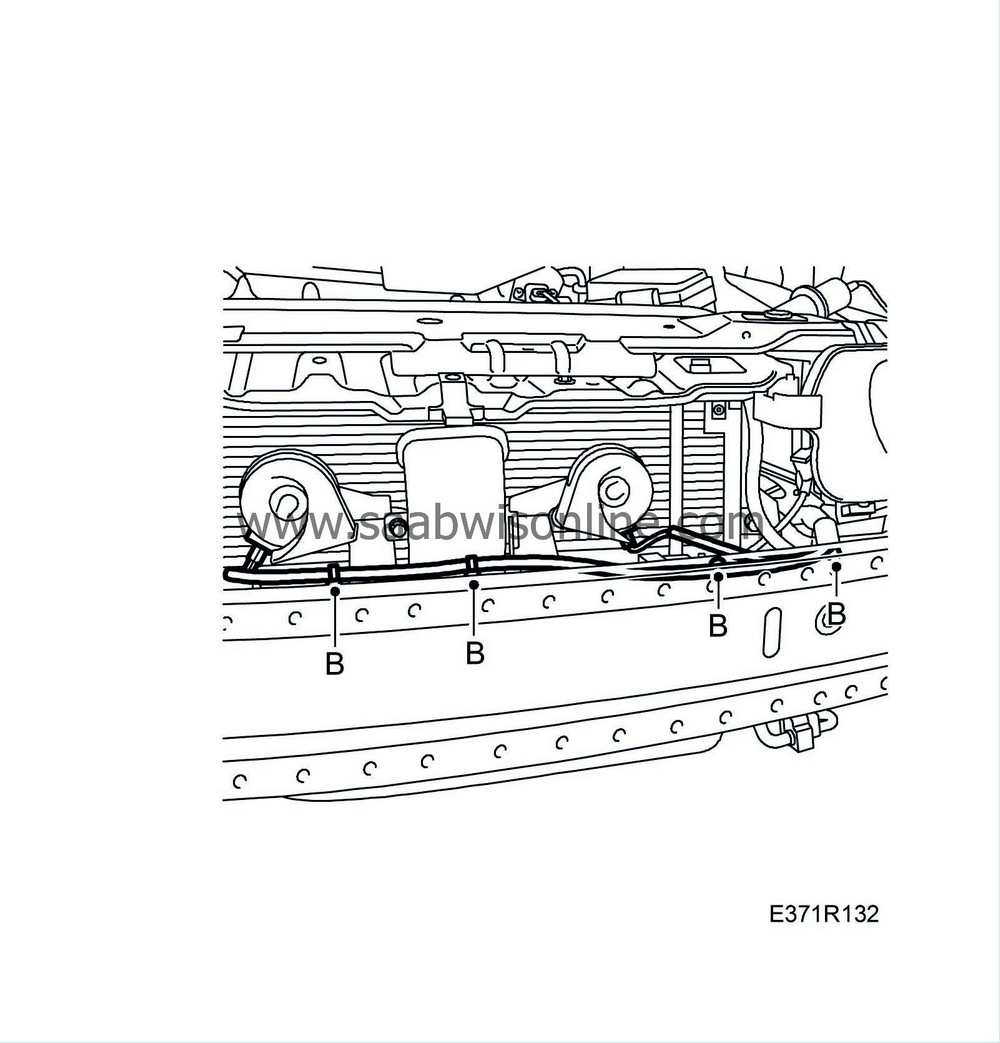
Remove the connectors (A) from the horn and remove the wiring harness fixings (B).
|
|
| 17. |
Remove the connectors from the impact sensors (A) and the condenser's pressure switch (B).

|
|
| 18. |
Remove the wiring harness clip (C).

|
|
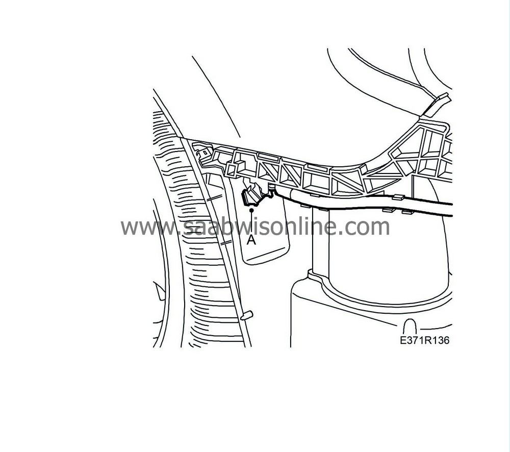
| 19. |
Remove the connector housing (A) from the holder.
|
|
| 20. |
Disconnect the connector to the AC compressor:
|
|
| • |
Undo the hose clips (A)

|
| • |
Remove the rubber bellows (B) for the mass air flow meter.
|
| • |
Disconnect the connector (C) to the AC compressor:

|
| 21. |
Disconnect the connector to the wheel sensor:
|
|
| • |
Remove the grounding point (A).

|
| • |
Remove the power steering reservoir (B).
|
| • |
Disconnect the connector (C) to the wheel sensor.
|
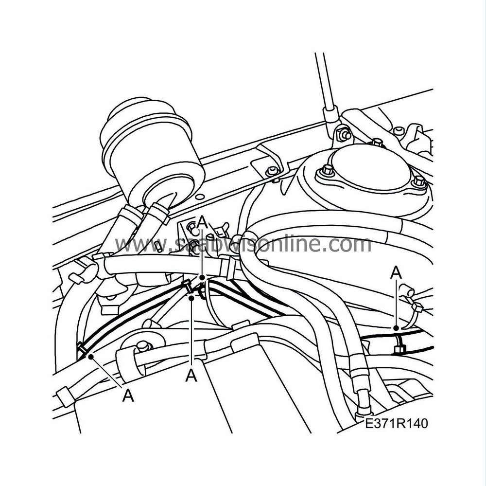
| 22. |
Remove the wiring harness fixings (A).
|
|
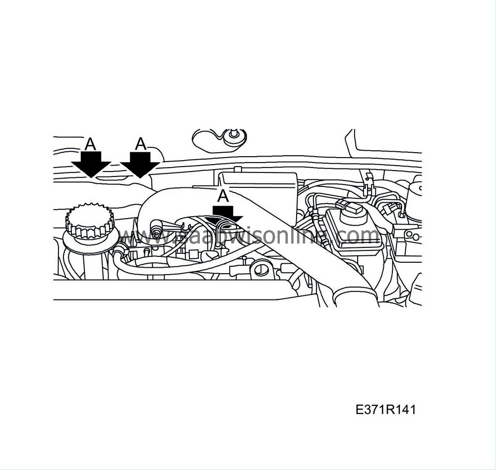
| 23. |
Remove the wiring harness fixings (A) at the bulkhead partition.
|
|
| 24. |
Remove the
bonnet contact
.
|
|
| 25. |
Remove the cable duct beneath the brake servo by undoing its clip.
|
|
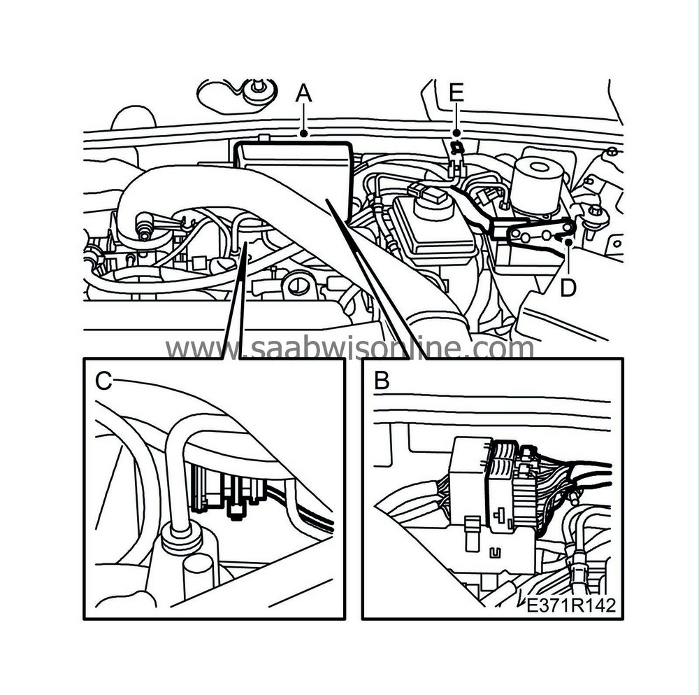
| 26. |
Remove the wiring harness from the ABS unit:
|
|
| • |
Remove the cover (A) and the connectors (B).
|
| • |
Remove the cable tie (C).
|
| • |
Remove the connector (D) from the ABS unit.
|
| • |
Remove the clip (E).
|
| 27. |
Lift out the wiring harness.
|
|
| To fit |
| Important | ||
|
Secure the wiring harness to prevent the risk of chafing and rattling. |
||
|
Check all rubber seals to minimize the risk of leakage. |
||
| Note | ||
|
Spray all connectors with contact spray in order to prevent verdigris formation, and clean and coat all grounding points with Vaseline. |
| 1. |
Place out the wiring harness.
|
|
| 2. |
Fit the wiring harness rubber grommet to the bulkhead partition.
|
|
| 3. |
Fit the wiring harness beneath the instrument panel:
|
|
| • |
Fit the connector (I) to the holder.

|
| • |
Fit the holder (H).
|
| • |
Plug in the connectors (D, E, F, G).
|
| • |
Connect the floor lighting connector.
|
| • |
Fit the data link connector (C).

|
| • |
Fit the cover (B).
|
| • |
Sort out the mat and fit the clip (A).
|
| 4. |
Fit the
sill protector
.
|
|
| 5. |
Fit the wiring harness to the ABS unit:
|
|
| • |
Plug in the connector (D) to the ABS unit.

|
| • |
Fit the clip (E).
|
| • |
Plug in the connectors (B) and fit the cover (A).
|
| • |
Fit the cable tie (C).
|
| 6. |
Fit the cable duct beneath the brake servo.
|
|
| 7. |
Fit the wiring harness fixings (A) at the bulkhead partition.

|
|
| 8. |
Fit the
bonnet contact
.
|
|
| 9. |
Plug in the connector to the wheel sensor:
|
|
| • |
Plug in the connector (C) to the wheel sensor.

|
| • |
Fit the power steering reservoir (B).
|
| • |
Fit the grounding point (A).
|
| 10. |
Remove the wiring harness fixings (A).

|
|
| 11. |
Plug in the connector to the AC compressor:
|
|
| • |
Plug in the connector (C) to the AC compressor.

|
| • |
Fit the rubber bellows (B) for the mass air flow meter.

|
| • |
Tighten the hose clips (A).
|
| 12. |
Plug in the connector (A) to the holder.

|
|
| 13. |
Plug in the connectors to the impact sensors (A) and the condenser's pressure switch (B).

|
|
| 14. |
Fit the wiring harness clip (C).

|
|
| 15. |
Fit the connectors (A) to the horn and fit the wiring harness fixings (B).

|
|
| 16. |
Plug in the connectors (A) for the headlamps.

|
|
| 17. |
Plug in the connectors (A) to the radiator fans and fit the cable tie (B).

|
|
| 18. |
Plug in the connector (A) to the wheel sensor and fit the grounding points (B).

|
|
| 19. |
Plug in the connector housings (A) for the washer pumps and washer fluid sensor (B).

|
|
| 20. |
Connect the siren connector:
|
|
| • |
Lift out the wheel arch liner and connect the siren connector (B).

|
| • |
Fit the screws (A) for the wheel arch liner.

|
| 21. |
Fit
bumper shell, front
.
|
|
| 22. |
Fit the cable duct:
|
|
| • |
Fit the cable duct mountings (B).

|
| • |
Snap on the cable duct cover (A).
|
| 23. |
Fit the cable (A) to the battery cable clip to the battery's positive terminal.

|
|
| 24. |
Plug in the connector (D) to the level sensor.

|
|
| 25. |
Fit the clip (C) to the coolant reservoir.
|
|
| 26. |
Fit the fuse box 342a:
|
|
| • |
Fit the nuts (A).
|
| • |
Fit the cable tie (B).
|
| 27. |
Fit the
battery shelf
.
|
|
| 28. |
Set the
time and date
and program in any radio code.
|
|

