Front Compartment Front Inner Side Rail Extension Replacement
| Front Compartment Front Inner Side Rail Extension Replacement |
| Removal Procedure |
Refer to Approved Equipment for Collision Repair Warning .
Refer to Collision Sectioning Warning .
Refer to Glass and Sheet Metal Handling Warning .
| 1. |
Disable the SIR system. Refer to
SIR Disabling and Enabling
.
|
|
| 2. |
Disconnect the negative battery cable. Refer to
Battery Negative Cable Disconnection and Connection
.
|
|
| 3. |
Visually inspect the damage. Repair as much of the damage as possible.
|
|
| 4. |
Remove the sealers and anti-corrosion materials from the repair area, as necessary. Refer to
Anti-Corrosion Treatment and Repair (Base)
Anti-Corrosion Treatment and Repair (Corrosion Protection)
.
|
|
| 5. |
Remove the front wheelhouse front liner. Refer to
Front Wheelhouse Front Liner Replacement
.
|
|
| 6. |
Remove the front wheelhouse rear liner. Refer to
Front Wheelhouse Rear Liner Replacement
.
|
|
| 7. |
Locate and drill out all of the battery tray support bracket factory welds.
|
|
| 8. |
Remove the front compartment upper side rail sectioning. Refer to
Front Compartment Upper Side Rail Sectioning
.
|
|
| 9. |
Remove the front wheelhouse front panel. Refer to
Front Wheelhouse Front Panel Replacement
.
|
|
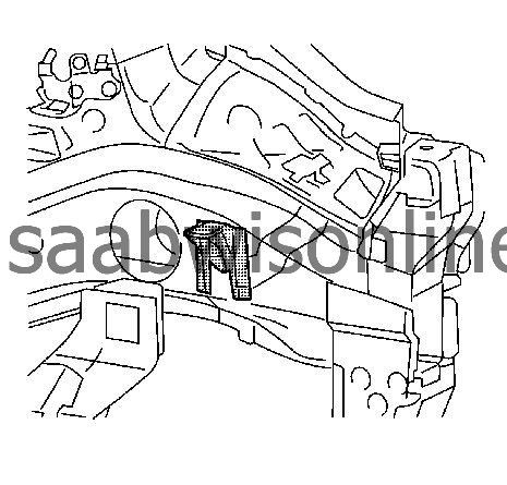
| 10. |
Cut out the front compartment front inner side rail extension. 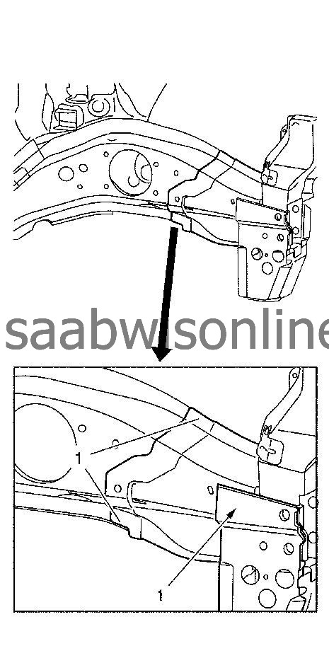
|
|||||||||||||
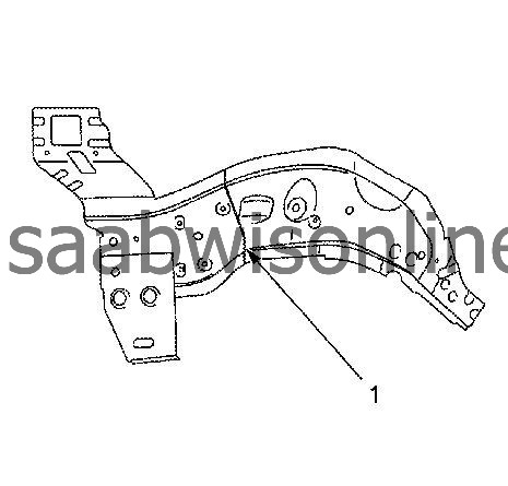
| 11. |
Locate and drill out all of the necessary factory welds (1).
|
|
| 12. |
Cut out the front compartment front outer side rail (1) 10 mm (0.4 in) staggered to the front compartment front inner side rail extension. 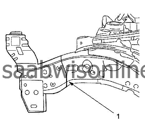
|
|||||||||||||
| 13. |
Remove the damaged front compartment front inner side rail extension and front compartment front outer side rail.
|
|
| Installation Procedure |
| 1. |
Prepare battery tray support bracket in the area (1).
4x slots 6x20 mm (0.2x0.7 in) |
|
| 2. |
Prepare the new front compartment front inner side rail extension in the areas:
|
|
| 2.1. |
2x slots
8x24 mm (0.3x0.9 in)
|
| 2.2. |
2x slots
8x24 mm (0.3x0.9 in)
|
| 3. |
Prepare the new front compartment front outer side rail in the area (1).
|
|
| 4. |
Cut the new front compartment front outer side rail section in the corresponding locations to fit the original panel. The sectioning joint should be trimmed to allow min. 1 times the metal thickness at the sectioning joint (1).
|
|
| 5. |
Apply bodywork repair through structural adhesive to body (1). Refer to Structural Adhesive Body Repairs . 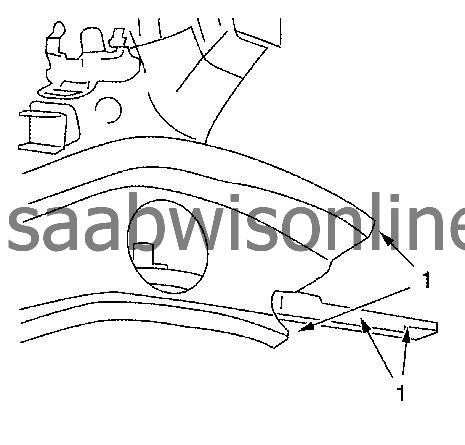
|
|||||||
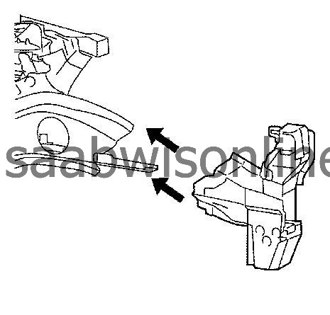
| 6. |
Position the front compartment front inner side rail extension onto the vehicle.
|
|
| 7. |
Verify the fit of the front compartment front inner side rail extension.
|
|
| 8. |
Clamp the front compartment front inner side rail extension into position.
|
|
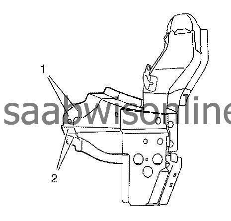
| 9. |
Spot weld (1) the front compartment front inner side rail extension accordingly. 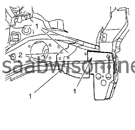
|
|||||||
| 10. |
MIG-braze (2) the front compartment front inner side rail extension.
|
|
| 11. |
Position the front compartment front outer side rail.
|
|||||||||||||
| 12. |
Verify the fit of the front compartment front outer side rail.
|
|
| 13. |
Clamp the front compartment front outer side rail into position.
|
|
| 14. |
MIG-braze (1) the front compartment front outer side rail.
|
|
| 15. |
Grind all MIG-brazed seams.
|
|
| 16. |
Spot weld (1) the front compartment front outer side rail accordingly. 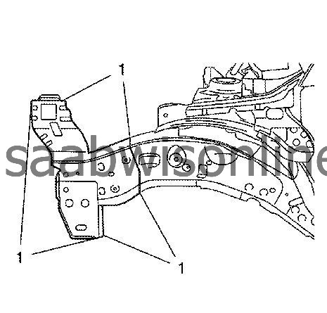
|
|||||||
| 17. |
Install the front wheelhouse front panel. Refer to
Front Wheelhouse Front Panel Replacement
.
|
|
| 18. |
Position the battery tray support bracket. 
|
|||||||
| 19. |
Verify the fit of the battery tray support bracket.
|
|
| 20. |
Clamp the battery tray support bracket into position.
|
|
| 21. |
MIG-braze (1) the battery tray support bracket.
|
|
| 22. |
Apply the sealers and anti-corrosion materials to the repair area, as necessary. Refer to
Anti-Corrosion Treatment and Repair (Base)
Anti-Corrosion Treatment and Repair (Corrosion Protection)
.
|
|
| 23. |
Install all related panels and components.
|
|
| 24. |
Install the front wheelhouse rear liner. Refer to
Front Wheelhouse Rear Liner Replacement
.
|
|
| 25. |
Install the front wheelhouse front liner. Refer to
Front Wheelhouse Front Liner Replacement
.
|
|
| 26. |
Connect the negative battery cable. Refer to
Battery Negative Cable Disconnection and Connection
.
|
|
| 27. |
Enable the SIR system. Refer to
SIR Disabling and Enabling
.
|
|
This project is supported by memberships and donations. If you use this site, please consider Joining SCNA and/or making a donation.
Our Friends
