Crankshaft and Bearing Removal
|
|
Crankshaft and Bearing Removal
|
Special Tools
|
•
|
GE 6125-1B
Slide Hammer Adapter
|
|
•
|
EN 49102
Crankshaft Bearing Cap Remover
|
For equivalent regional tools, refer to
Special Tools
.
|
Crankshaft End Play Measurement
|
|
1.
|
Place a dial indicator at the crankshaft nose.
|
|
2.
|
Gently force the crankshaft to the extreme front and rear positions with a pry tool while monitoring the movement of the dial indicator.
|
|
5.
|
Replace the thrust bearing or crankshaft as necessary.
|
|
1.
|
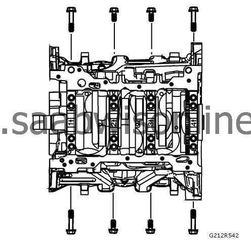
Remove the crankshaft bearing cap side bolts.
|
|
2.
|
Remove the crankshaft bearing cap outer bolts.
|
|
3.
|
Remove the crankshaft bearing cap inner bolts.
|
|
4.
|
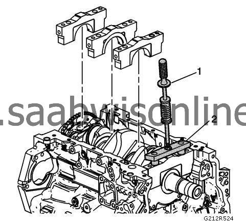
Remove the crankshaft bearing caps using the
GE 6125-1B
adapter (1) and
EN 49102
remover (2).
|
|
5.
|
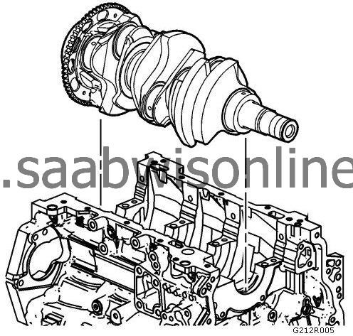
Using 2 hands, lift the crankshaft straight up from the engine block.
|
|
6.
|
Place the crankshaft in a secure place.
|
|
7.
|
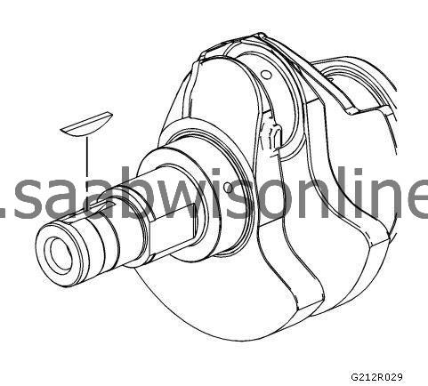
Remove the crankshaft key from the nose of the crankshaft, if damaged.
|
|
Crankshaft Bearing Removal
|
|
1.
|
Prepare a piece of cardboard or equivalent, numbered 1-4 for bearing identification. Main bearing journals are numbered from the front of the engine.
|
|
2.
|
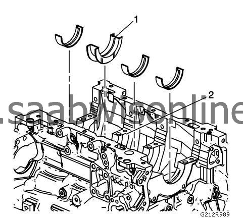
Remove the crankshaft upper bearing halves from the cylinder block. Note the position of the thrust bearing (1) at the number 3 journal (2).
|
|
3.
|
Place the crankshaft upper bearing halves on the cardboard in the correct positions. Note that the number 3 bearing is the thrust bearing.
|
|
4.
|
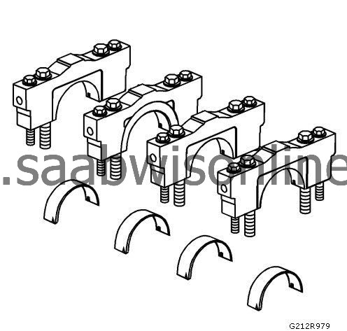
Remove the crankshaft lower bearing halves from the crankshaft bearing caps.
|
|
5.
|
Place the crankshaft lower bearing halves in the correct positions on the cardboard.
|


