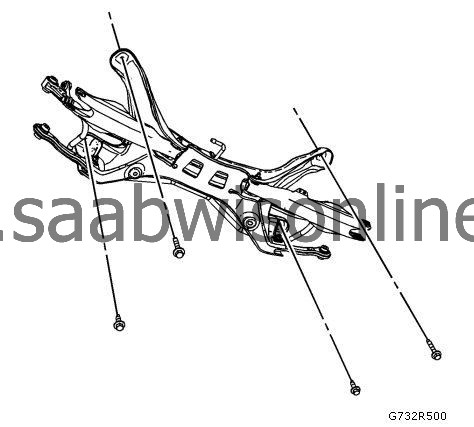
Rear Suspension Support Replacement (GNC)
| Rear Suspension Support Replacement (GNC) |
Removal Procedure
| 1. |
Raise and support the vehicle. Refer to
Lifting and Jacking the Vehicle
.
|
|
| 2. |
Remove the rear tire and wheel assemblies. Refer to
Tire and Wheel Removal and Installation
.
|
|
| 4. |
Disconnect the stabilizer shaft from stabilizer shaft links. Refer to
Stabilizer Shaft Replacement (GNC)
Stabilizer Shaft Replacement (GNE FWD)
.
|
|
| 5. |
Remove the park brake cables from the support. Refer to
Parking Brake Rear Cable Replacement (J71)
.
|
|
| 6. |
Remove the lower control arms from the vehicle.
|
|
| 7. |
Remove the adjust links from the from the vehicle. Refer to
Adjust Link Replacement (GNC)
Adjust Link Replacement (GNE)
.
|
|
| 8. |
Remove the upper control arm inner fasteners.
|
|
| 9. |
Position a transmission jack under the rear support and firmly secure the support to the jack with straps.
|
|
| 10. |
Mark the location of the frame using spray paint for correct positioning during installation.
|
|
| 11. |
Remove the support bolts and discard them.
|
|
| 12. |
With the aid of an assistant, lower the support from the transmission jack stand.
|
|
| 13. |
Remove the stabilizer shaft from the rear support.
|
|
| Installation Procedure |
| 1. |
Install the stabilizer shaft assembly on to the support. Refer to Stabilizer Shaft Replacement (GNC) Stabilizer Shaft Replacement (GNE FWD) . |
|||||||
| 2. |
With the aid of an assistant, position the rear support onto the transmission jack and firmly secure the support to the jack with straps.
|
|
| 3. |
Carefully lower the vehicle until contacts the frame assembly and is correctly positioned within the spray painted areas.
|
|
| 4. |
Refer to
Fastener Caution
.
Install the NEW support bolts and tighten to 90 Nm (66 lb ft) .
|
|
| 5. |
Tighten the support bolts an additional
120 degrees + 15 degrees
.
|
|
| 6. |
Remove the transmission jack stand.
|
|
| 7. |
Install the upper control arm inner fasteners.
|
|
| 8. |
Install the adjust links to the support. Refer to
Adjust Link Replacement (GNC)
Adjust Link Replacement (GNE)
.
|
|
| 9. |
Install the lower control arms.
|
|
| 10. |
Install the park brake cables to the rear support. Refer to
Parking Brake Rear Cable Replacement (J71)
.
|
|
| 12. |
Connect the stabilizer shaft links to the stabilizer shaft. Refer to
Stabilizer Shaft Replacement (GNC)
Stabilizer Shaft Replacement (GNE FWD)
.
|
|
| 13. |
Install the rear tire and wheel assemblies. Refer to
Tire and Wheel Removal and Installation
.
|
|
| 14. |
Lower the vehicle.
|
|
| 15. |
Realign the rear suspension. Refer to
Wheel Alignment Measurement
.
|
|
This project is supported by memberships and donations. If you use this site, please consider Joining SCNA and/or making a donation.
Our Friends
