SAAB WIS ONLINE

B1228

B1228

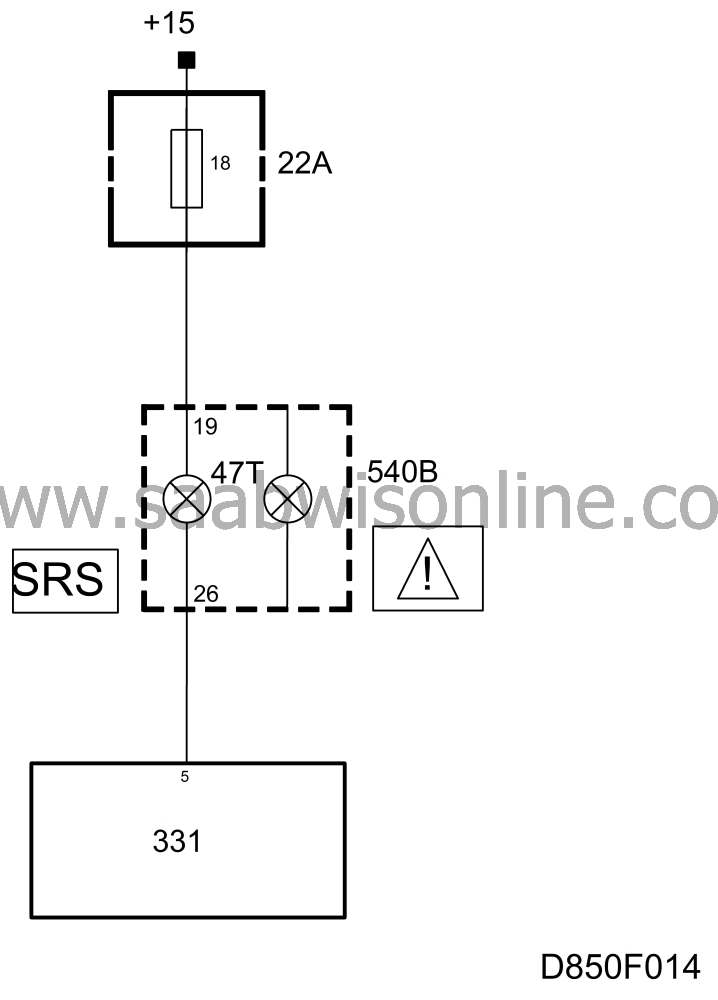
Bulb 1 in the SRS symbol, burnt out, open circuit in the wiring or short circuit to ground (bulb connected to control module pin 5).

Cars with central warning lamp


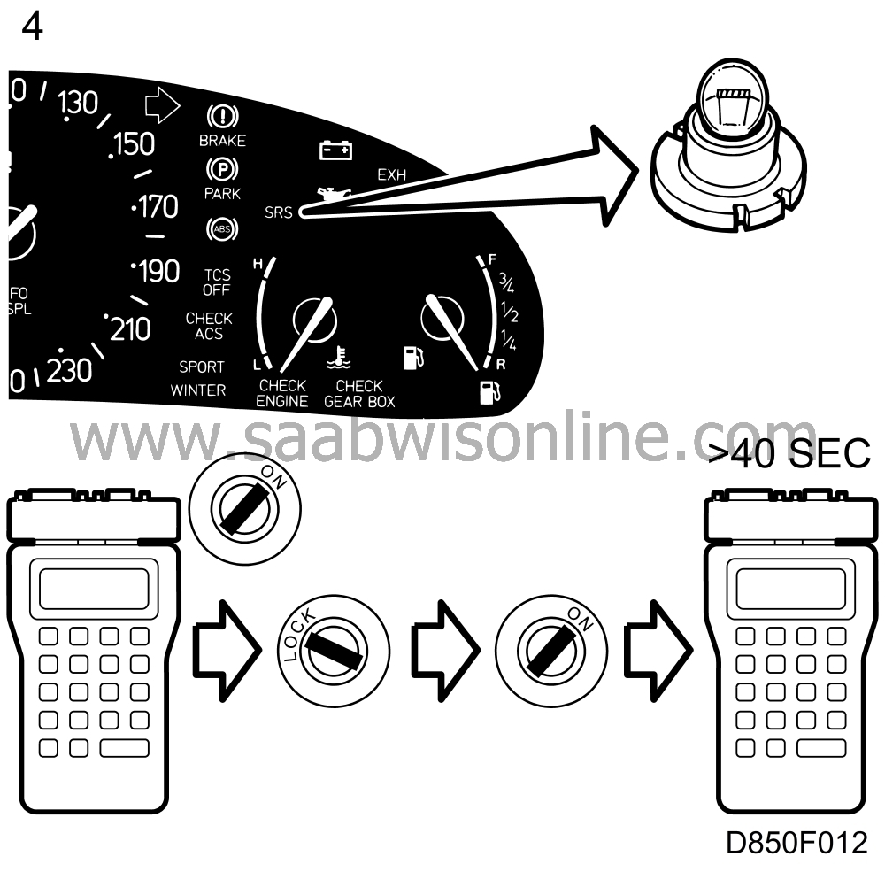
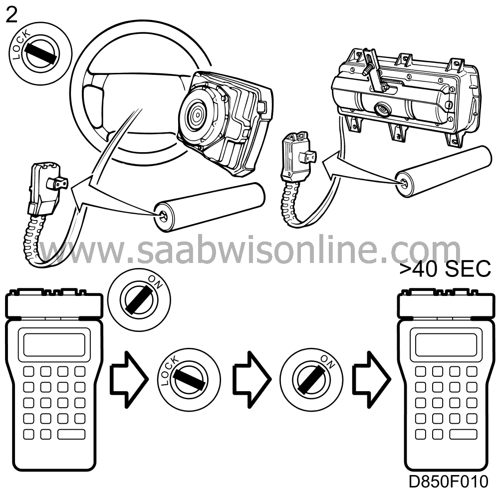
1. Make a note of the diagnostic trouble code and then clear it. Switch the ignition off and on again, wait for at least 40 seconds with the ignition switched on and check to see whether the diagnostic trouble code recurs.

If it does, it is a permanent fault. Proceed to point 2.

If it does not, the fault is intermittent.

Leave the ignition switched on and jiggle the connectors and wiring to check for an open circuit or loose contact. Switch the ignition off and then on again. With the ignition switched on, wait for at least 40 seconds and then check whether the diagnostic trouble code recurs.

2. Unscrew the steering wheel airbag and unplug the connector at the back of the airbag. Connect reference resistor 84 71 153 to the connector.

On cars with a passenger airbag, remove the glove box, unplug the connector on the underside of the passenger airbag and connect reference resistor 84 71 153 to the connector.

If the SRS lamp remains on continuously after the ignition has been switched on, proceed to point 6.

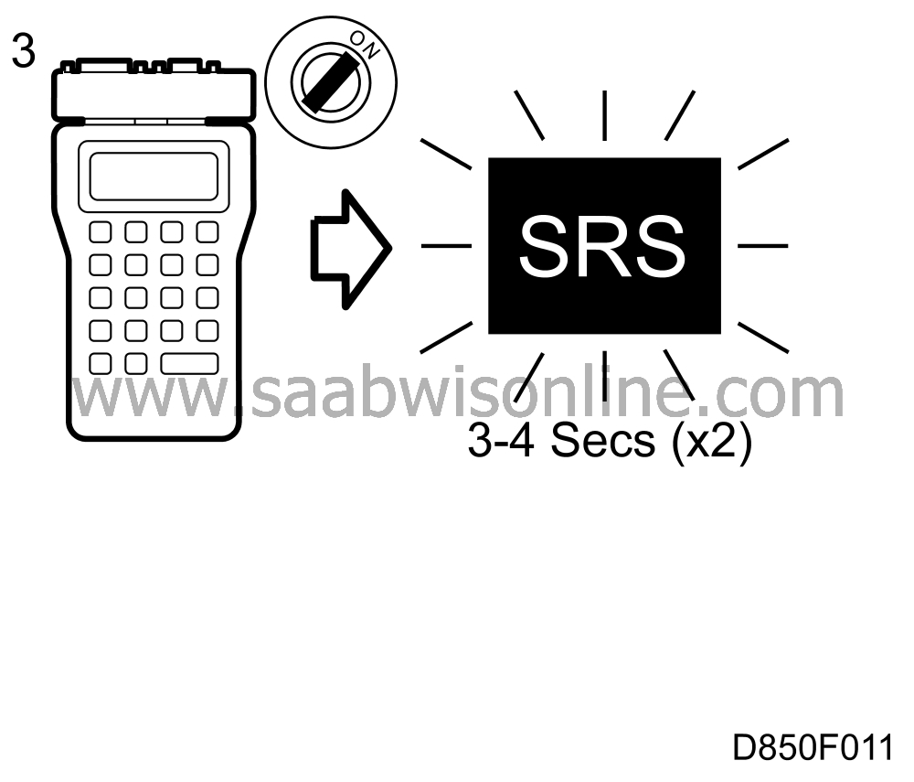
3. Switch on the ignition and test bulb 1 by entering the command "TURN ON SRS1 LAMP" on the ISAT scan tool. The lamp should then come on for 3-4 seconds twice in succession.


If the lamp does not come on, proceed to point 4.

If the lamp comes on, proceed to point 5.

4. Change the bulb. Switch on the ignition and enter the command "TURN ON SRS1 LAMP" on the ISAT scan tool. The lamp should then come on for 3-4 seconds twice in succession.


If the lamp does not come on, proceed to point 5.

If the lamp comes on, clear the diagnostic trouble code. Switch the ignition off and then on again, wait for at least 40 seconds and check to see whether the diagnostic trouble code recurs.

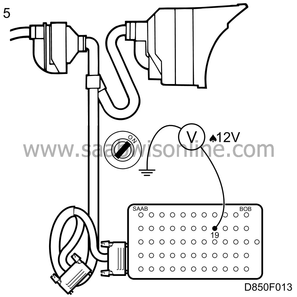
5. Unplug the connector behind the main instrument unit and connect a BOB to the connector. Switch on the ignition and take a voltage reading across pin 19 and a good grounding point.


If no battery voltage is present, check the wiring between the connector and fuse 18 for an open circuit or contact pin slide-out.

Rectify the fualt and proceed to point 7.

If battery voltage is present, proceed to point 6.

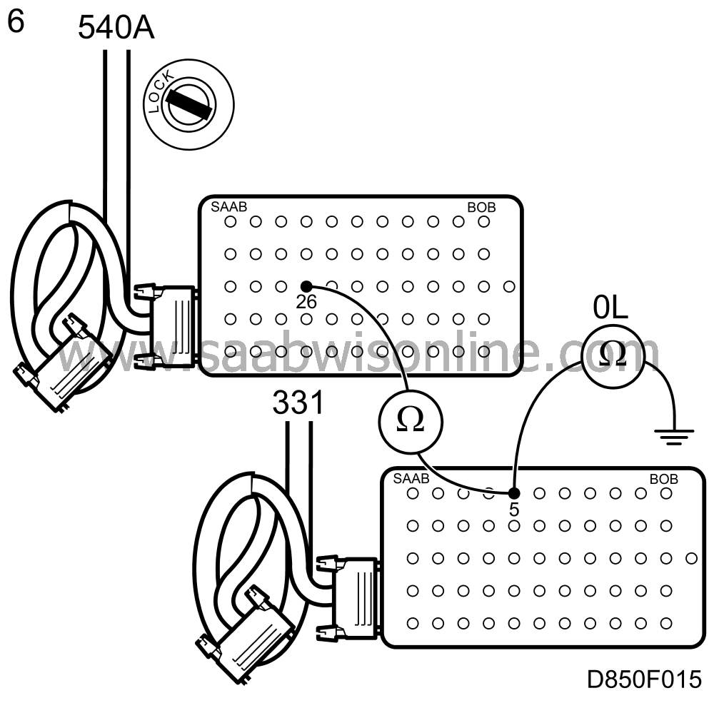
6. Switch off the ignition, unplug the connector behind the main instrument unit and connect a BOB to the plug (if this was not already done in point 5).


Unplug the connector from the control module, open it and check the functioning of the short circuit contact between pins 5 and 3. Connect a BOB to the connector. Take a resistance reading across pin 26 on the BOB connected to the main instrument unit and pin 5 on the BOB connected to the control module.

If the resistance is high, check the wiring between the main instrument unit and control module for open circuit/contact pin slide-out.

Rectify the fualt and proceed to point 7.

If the resistance is low, take a resistance reading across pin 5 on the BOB connected to the control module and a good grounding point. If this reading shows low resistance, there is a leakage to ground.

Investigate the cause and remedy the fault.

If the resistance reading is high, proceed to point 7.

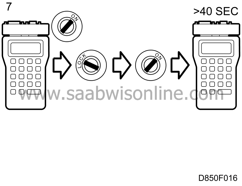
7. Plug in the connectors, switch on the ignition and clear the diagnostic trouble code. Switch the ignition off and on again, wait for at least 40 seconds and then check to see whether the diagnostic trouble code recurs.


If the diagnostic trouble code recurs, continue fault diagnosis as described in Service Manual 3:5 under main instrument unit . If the fault persists after this, proceed to .