ISAT scan tool communicationfaulty
Symptom: No ISAT scan tool communication.
|
|
ISAT scan tool communication
faulty
|
Fault symptom
No ISAT scan tool communication.
Condition
|
•
|
The control module has no power
supply (+15 circuit).
|
|
•
|
The control module has no connection to ground.
|
|
•
|
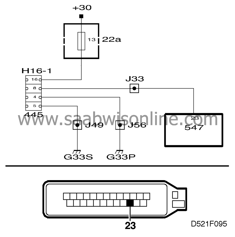
No continuity in the data link connector (H16-1)
circuit.
|
Diagnostic procedure
1 Check the control module's power supply and connection to
ground
|
-
|
Unplug the control module's
4-pin connector. Ignition switch in the ON position. Take voltage readings on the control
module's connector. Connect the voltmeter,
|
|
|
•
|
to battery positive (B+) and pin 1 =
<0.5 V
|
|
|
•
|
to battery positive (B+) and pin 2 = <0.5 V
|
|
|
•
|
to pin 3 and battery negative (B-) = <0.1 V
|
Are all voltage readings OK?
Continue with point 2.
Check the wiring harness, including connectors, and grounding point G30.
Repair or replace as necessary.
2 Check the ISAT scan tool connector


|
-
|
Plug in the ISAT scan tool. The
ISAT scan tool"s display should light up.
|
Is the ISAT scan tool"s display alight?
Continue with point 5.
Continue with point 3.
3 Check the data link connector's power supply (+30
circuit)

|
-
|
Connect the test lamp to pin 16 of
the data link connector and a good grounding point. The test lamp should light
up.
|
Does the test lamp light up?
Continue with point 4.
Check fuse 13 and change it if necessary. If the fuse is intact, check and if
necessary rectify:
1) the lead between fuse 13 and pin 16 of the data link connector,
2) the supply of current up to fuse 13, as described in Service Manual 3:2 Electrical
system, wiring diagram, power supply.
4 Check the data link connector's connection to
ground

|
-
|
Connect the test lamp to data link
connector
|
|
|
•
|
pins 5 and 16
The test lamp should light up in both cases.
|
Does the test lamp light up?
Continue with point 5.
Check and if necessary repair or replace the lead
|
•
|
between pin 4 and grounding point
G33P
|
|
•
|
between pin 5 and grounding point G33S.
|
5 Check ISAT scan tool communication

|
-
|
Fit the control module. Select ABS
”M94/95” The ISAT scan tool should display the system menu for the
ABS.
|
Does the ISAT scan tool display the system menu?
The fault is of an intermittent nature.
Continue with point 6.
6 Check ISAT scan tool communication with another
system

|
-
|
Select another system included in
the car's equipment. The ISAT scan tool should display the selected system's
menu.
|
Does the ISAT display the selected system's menu?
Continue with point 7.
Check the ISAT scan tool, see Service Manual 1:5 Diagnosis and fault-
tracing.
7 Check the wiring

|
-
|
Check the lead for continuity
between pin 11 (25-pin connector) of the control module and pin 8 of the data link
connector.
|
Is the lead OK?
Continue with point 8.
Rectify the fault.
8 Final check

|
-
|
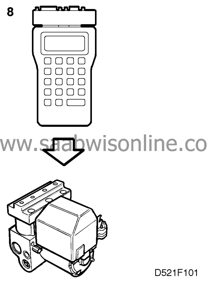
Using the ISAT scan tool, call up
ABS M94/95.
|
Does ABS M94/95 answer?
The diagnostic procedure carried out was correct.
Continue with


