Gear selector position sensor
|
|
Gear selector position sensor
|
|
Important
|
|
Before removing the gear selector position sensor, its values should be measured with the Scan tool diagnostics instrument in accordance with the procedure described in
 .
.
|
|
Avoid removing the gear selector position sensor as far as possible, as it could easily be damaged in the process.
|
|
|
|
1.
|
Remove the pressure pipe between the charge air cooler and throttle body and seal the hose to prevent dirt from entering it.
|
|
2.
|
Lift up the power steering fluid reservoir and move it aside.
|
|
3.
|
Unplug the three sensor connectors.
|
|
4.
|
Press the connectors out of the holder.

|
|
5.
|
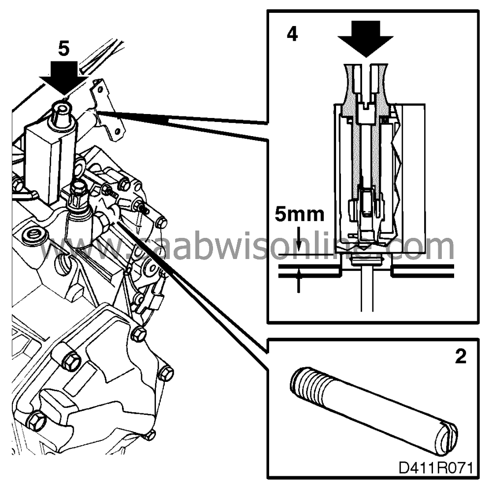
Undo the three screws and lift out the holder.
|
|
6.
|
Look for the sensors' wiring harness and pull it towards the radiator.

|
|
7.
|
Snip the wiring harness cable ties.
|
|
8.
|
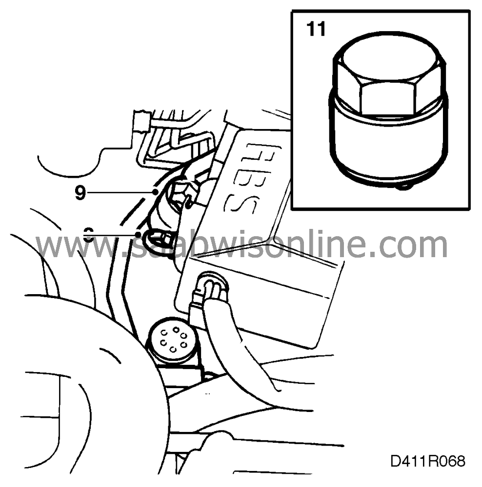
Undo or cut the clip securing the AC pipe above the gear selector position sensor.

|
|
9.
|
Move the AC pipe outwards so that the gear selector position sensor can be pulled straight up.
|
|
11.
|
Unscrew the gear selector position sensor's cap, using tool 87 92 434.
|
|
12.
|
Slacken the gear selector position sensor's retaining bolt 5 turns (about 5 mm) and lift up the sensor so that the O-ring releases. Press tool 87 92 509 down with the pin in the hole until it hooks in the passage under the threads. The transit tool secures the inner part of the sensor and prevents it from turning. If the sensor is to be reused, the tool must be left in place until the sensor has been fitted.

|
Important
|
|
It is extremely important to ensure that the tool is fitted correctly and that the gear selector position sensor does not turn. Otherwise the sensor will be rendered unserviceable.
|
|
|
|
|
13.
|
Remove the gear selector position sensor's retaining screw and fit locating pin 83 94 736 in the hole.
|
|
14.
|
Lift the gear selector position sensor straight up out of the gearbox.
|
|
15.
|
Extract the gear selector position sensor's shaft from the gearbox if it did not come out when the sensor was removed. Protect the sealing surfaces with a cloth.
|
Important
|
|
A gear selector position sensor should not normally be reused as even careful removal of the sensor could damage it internally.
|
|
|
|

|
Important
|
|
The gear selector position sensor is highly sensitive and it is known from experience that many sensors are damaged in connection with their installation.
|
|
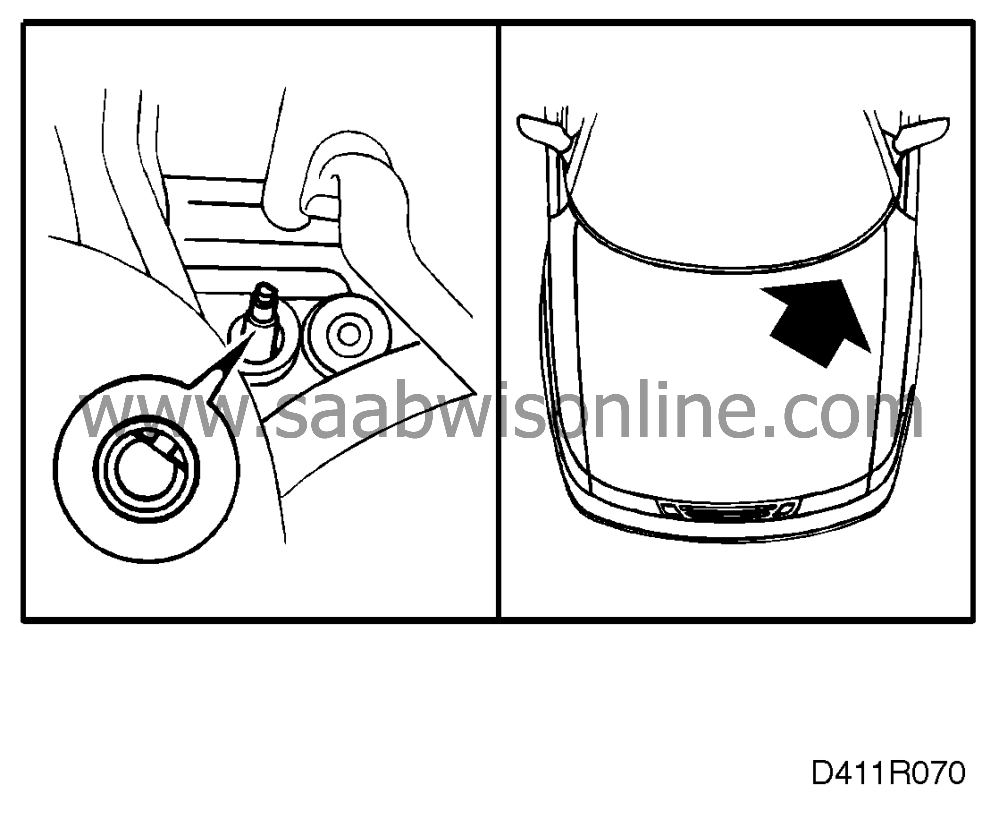
In connection with refitting an old gear selector position sensor, the shaft must be inspected for damage. If it is damaged, a new shaft must be used. The shaft should be fitted separately in the gearbox. The flat side at the top of the shaft should face the left-hand front door, see illustration, when 2nd gear is engaged. Press the shaft home until a click is heard.
|
|
The new gear selector position sensor incorporates a tool which must not be removed before installation.
|
|
The sensor must not be turned during the fitting process as this could damage it.
|
|
|
|
1.
|
Make sure that 2nd gear is engaged.

|
|
2.
|
Fit locating pin 83 94 736 in the hole for the gear selector position sensor's retaining screw.
|
|
3.
|
Supplied with the new gear selector position sensor is a shaft of plastic.
|
|
4.
|
Carefully fit the new gear selector position sensor vertically until the shaft bottoms in the gearbox. This corresponds to a distance of about 5 mm between the gear selector position sensor and the gearbox. The locating pin is designed to ensure that the gear selector position sensor is correctly seated.
|
|
5.
|
Press down on the transit tool so that the gear selector position sensor snaps into place in the gearbox.
|
|
6.
|
Remove the transit tool.

|
|
7.
|
Remove the locating pin and fit the gear selector position sensor's retaining screw.
|
|
8.
|
Using tool 87 92 418, check that the sensor's shaft has been fitted in its correct position in the gear selector position sensor. It should be possible to rotate the tool through 360 without the slightest resistance.
|
|
9.
|
Fit the gear selector position sensor's cap, using tool 87 92 434.
|
|
10.
|
Fit the A/C pipe in place with new clips and check the clip for the power steering pipe and A/C pipe under the clutch actuator unit.
|
|
11.
|
Secure the sensor's lead to the wiring harness using new cable ties.

|
|
12.
|
Correctly position the wiring harness, secure the connectors in the holder and screw in the holder's three retaining bolts.
|
|
13.
|
Plug in the three sensor connectors. If the old gear selector position sensor has been refitted, its values must be measured again in accordance with the procedure described in
 . These values should lie within the limits shown in the table and should preferably be identical to the readings obtained before the sensor was removed.

|
|
14.
|
Refit the power steering fluid reservoir.
|
|
15.
|
Refit the pressure pipe.
|
|
16.
|
Program the control module with the Scan tool diagnostics instrument, "MEMORIZING GEAR POSITION".
|
|
3.
|
By means of the Scan tool diagnostics instrument's "READ FUNCTIONS" menu, read the gear position and voltages recorded by the sensor. The gear lever must not be touched while this is being done.
|
|
4.
|
Note the readings obtained.
|
|
5.
|
Repeat the procedure for all gears.
|
Gear position
|
Gear position, lengthwise (V)
|
Gear position, crosswise (V)
|
Engaged
|
According to the Scan tool diagnostics instrument
|
Nom.
|
Measured according to the Scan tool diagnostics instrument
|
Nom.
|
Measured according to the Scan tool diagnostics instrument
|
1
|
|
0.3-2.0
|
|
3.6-4.7
|
|
2
|
|
3.5-4.7
|
|
3.6-4.7
|
|
3
|
|
0.3-2.0
|
|
2.4-3.6
|
|
4
|
|
3.5-4.7
|
|
2.4-3.6
|
|
5
|
|
0.3-2.0
|
|
0.3-2.4
|
|
R
|
|
3.5-4.7
|
|
0.3-2.4
|
|


 . These values should lie within the limits shown in the table and should preferably be identical to the readings obtained before the sensor was removed.


