Test readings, control module connections
| Test readings, control module connections |
| Remember |
| • |
Note the test conditions, and use common sense when assessing the test results.
|
|
| • |
The specified readings are with the ignition in position ON unless stated otherwise.
|
|
| • |
First check that the control module is supplied with current and is grounded.
|
|
| • |
Then check all sensor inputs and signals from other systems.
|
|
| • |
Finally, check the control module outputs. Remember that the test readings do not indicate whether the actuator is working.
|
|
| • |
If any reading is not OK, consult the wiring diagram to trace the leads, connectors or components that ought to be checked more thoroughly.

|
|
| • |
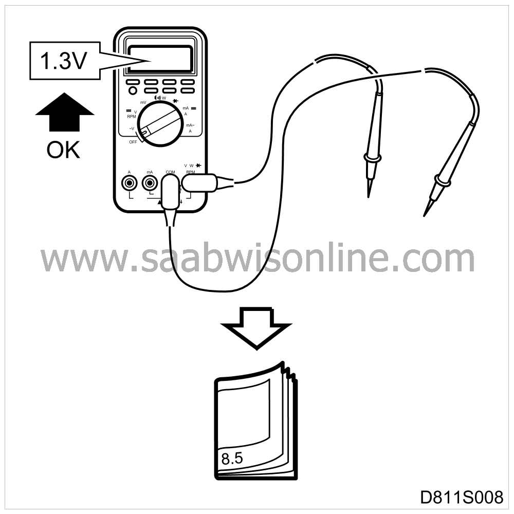
The test readings given apply to a calibrated Fluke 88/97.
|
|
| • |
The test readings show the signal's pulse ratio and pulse width. A test instrument with pulse ratio and pulse width measurement must be used. The (+) sign indicates a positive trigger pulse, TRIG+.
|
|

| Important | ||
|
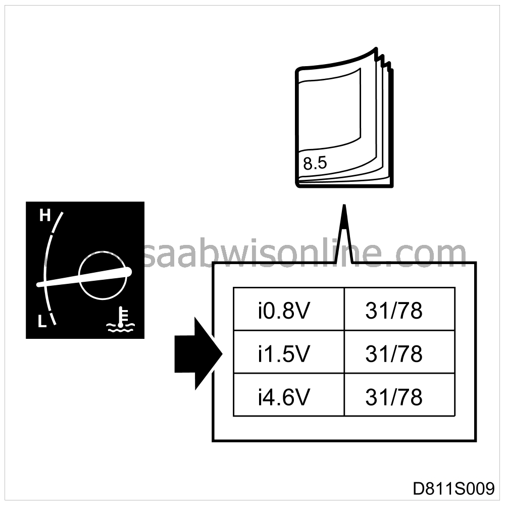
The control module processor must not be in a state of rest when the control module connections are being tested. See
|
||
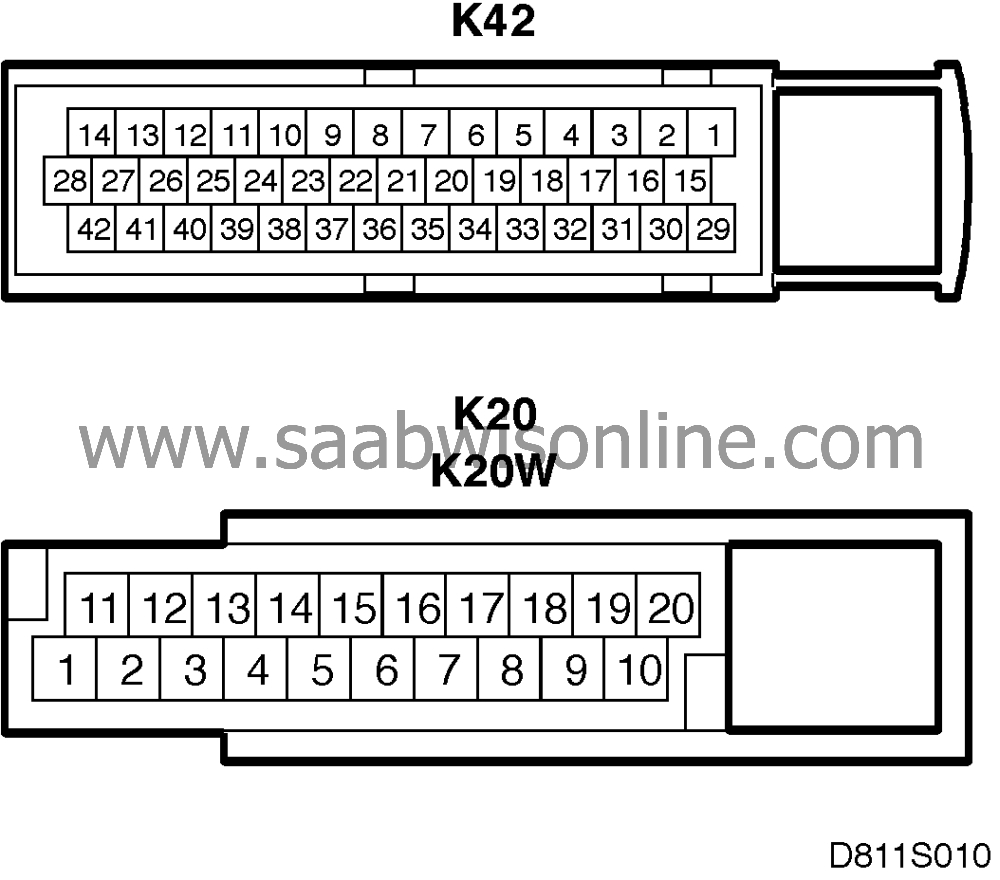
| Pin | BOB no. | Component/function | In/Out | Test conditions | Across X-Y | Test reading (V) | |
|
1 (K42)
|
1
|
|
Window switch, front right UP
|
In
|
Switch inactive
Switch active |
1-18
|
0 V
12 V |
|
2 (K42)
|
2
|
|
Window switch, front right DOWN
|
In
|
Switch inactive
Switch active |
2-18
|
0 V
12 V |
|
3 (K42)
|
3
|
|
Window switch, rear left UP
|
In
|
Switch inactive
Switch active |
3-18
|
0 V
12 V |
|
4 (K42)
|
4
|
|
Window switch, rear left DOWN
|
In
|
Switch inactive
Switch active |
4-18
|
0 V
12 V |
|
5 (K42)
|
5
|
|
Window switch, rear right UP
|
In
|
Switch inactive
Switch active |
5-18
|
0 V
12 V |
|
6 (K42)
|
6
|
|
Window switch, rear right DOWN
|
In
|
Switch inactive
Switch active |
6-18
|
0 V
12 V |
|
7 (K42)
|
7
|
|
Luggage compartment switch
|
In
|
Lid open
Lid closed |
7-18
|
0 V
12 V |
|
8 (K42)
|
8
|
|
No connection
|
|
|
|
|
|
9 (K42)
|
9
|
|
No connection
|
|
|
|
|
|
10 (K42)
|
10
|
|
DIAGNOSTICS K-lead
|
In/Out
|
Diagnostic tool connected
|
10-18
|
approx. 10 V
|
|
11 (K42)
|
11
|
|
Information bus SID unit
|
Out
|
|
11-18
|
Varying voltage 0-12 V
|
|
12 (K42)
|
12
|
|
Speed signal Right rear wheel
|
In
|
Rotate right rear wheel 1/2 rev/second
|
12-18
|
approx. 15 Hz
|
|
13 (K42)
|
13
|
|
No connection
|
|
|
|
|
|
14 (K42)
|
14
|
|
No connection
|
|
|
|
|
|
15 (K42)
|
15
|
|
Power supply potentiometers
|
Out
|
|
15-18
|
5 V
|
|
16 (K42)
|
16
|
|
No connection
|
|
|
|
|
|
17 (K42)
|
17
|
|
No connection
|
|
|
|
|
|
18 (K42)
|
18
|
|
Signal ground
|
In
|
|
18-52
|
< 0.1 V
|
|
19 (K42)
|
19
|
|
No connection
|
|
|
|
|
|
20 (K42)
|
20
|
|
No connection
|
|
|
|
|
|
21 (K42)
|
21
|
|
No connection
|
|
|
|
|
|
22 (K42)
|
22
|
|
Supply microswitch inactive position
|
Out
|
|
22-18
|
approx. 2.1 V
|
|
23 (K42)
|
23
|
|
Supply microswitch active position
|
Out
|
|
23-18
|
approx. 0.7 V
|
|
24 (K42)
|
24
|
|
Microswitch roof latch left
|
In
|
Active
Inactive |
24-18
|
approx. 0.7 V
approx. 2.1 V |
|
25 (K42)
|
25
|
|
Microswitch 5th bow left
|
In
|
Active
Inactive |
25-18
|
approx. 0.7 V
approx. 2.1 V |
|
26 (K42)
|
26
|
|
Microswitch soft top cover left
|
In
|
Active
Inactive |
26-18
|
approx. 0.7 V
approx. 2.1 V |
|
27 (K42)
|
27
|
|
Microswitch soft top storage left
|
In
|
Active
Inactive |
27-18
|
approx. 0.7 V
approx. 2.1 V |
|
28 (K42)
|
28
|
|
Switch soft top operation UP
|
In
|
Inactive
Active |
28-18
|
0 V
12 V |
|
29 (K42)
|
29
|
|
Ground potentiometers
|
In
|
|
29-18
|
< 0.1 V
|
|
30 (K42)
|
30
|
|
Main motor position potentiometer
|
In
|
Soft top in: top position bottom position
|
30-18
|
approx. 4 V
approx. 0.7 V |
|
31 (K42)
|
31
|
|
5th bow position potentiometer
|
In
|
5th bow in: top position bottom position
|
31-18
|
approx. 4 V
approx. 0.7 V |
|
32 (K42)
|
32
|
|
Soft top cover position potentiometer
|
In
|
Soft top cover in: top position
bottom position |
32-18
|
approx. 4 V
approx. 1.2 V |
|
33 (K42)
|
33
|
|
No connection
|
|
|
|
|
|
34 (K42)
|
34
|
|
No connection
|
|
|
|
|
|
35 (K42)
|
35
|
|
No connection
|
|
|
|
|
|
36 (K42)
|
36
|
|
No connection
|
|
|
|
|
|
37 (K42)
|
37
|
|
No connection
|
|
|
|
|
|
38 (K42)
|
38
|
|
Microswitch roof latch right
|
In
|
Active
Inactive |
38-18
|
approx. 0.7 V approx. 2.1 V
|
|
39
|
39
|
|
No connection
|
|
|
|
|
|
40 (K42)
|
40
|
|
Microswitch soft top cover right
|
In
|
Active
Inactive |
40-18
|
approx. 0.7 V approx. 2.1 V
|
|
41 (K42)
|
41
|
|
Microswitch soft top storage right
|
In
|
Active
Inactive |
41-18
|
approx. 0.7 V approx. 2.1 V
|
|
42 (K42)
|
42
|
|
Switch soft top operation DOWN
|
In
|
Active
Inactive |
42-18
|
12 V
0 V |
|
1 (K20)
|
43
|
|
Main motor UP
|
Out
|
Motor inactive Motor running
|
43-52
|
0 V
12 V |
|
2 (K20)
|
44
|
|
5th bow latch motor UNLOCKING
|
Out
|
Motor inactive Motor running
|
44-52
|
0 V
12 V |
|
3 (K20)
|
45
|
|
No connection
|
|
|
|
|
|
4 (K20)
|
46
|
|
No connection
|
|
|
|
|
|
5 (K20)
|
47
|
|
No connection
|
|
|
|
|
|
6 (K20)
|
48
|
|
No connection
|
|
|
|
|
|
7 (K20)
|
49
|
|
No connection
|
|
|
|
|
|
8 (K20)
|
50
|
|
No connection
|
|
|
|
|
|
9 (K20)
|
51
|
|
+15
|
In
|
|
Batt+ - 51
|
< 0.5 V
|
|
10 (K20)
|
52
|
|
Power ground
|
In
|
Soft top in motion
|
52- Batt-
|
< 0.2 V
|
|
11 (K20)
|
53
|
|
Main motor DOWN
|
Out
|
Motor inactive Motor running
|
53-52
|
0 V
12 V |
|
12 (K20)
|
54
|
|
5th bow latch motor LOCKING
|
Out
|
Motor inactive Motor running
|
54-52
|
0 V
12 V |
|
13 (K20)
|
55
|
|
5th bow motor UP
|
Out
|
Motor inactive Motor running
|
55-52
|
0 V
12 V |
|
14 (K 20)
|
56
|
|
5th bow motor DOWN
|
Out
|
Motor inactive Motor running
|
56-52
|
0 V
12 V |
|
15 (K 20)
|
57
|
|
No connection
|
|
|
|
|
|
16 (K 20)
|
58
|
|
Soft top cover motor DOWN
|
|
Motor inactive Motor running
|
58-52
|
0 V
12 V |
|
17 (K 20)
|
59
|
|
Soft top cover motor UP
|
|
Motor inactive Motor running
|
59-52
|
0 V
12 V |
|
18 (K 20)
|
60
|
|
Luggage compartment lock motor
|
|
Motor inactive Motor running
|
60-52
|
0 V
12 V |
|
19 (K 20)
|
61
|
|
Opening button in driver's door
|
In
|
Active
Inactive |
61-18
|
12 V
0 V |
|
20 (K 20)
|
62
|
|
+30
|
In
|
Soft top in motion
|
Batt+-62
|
< 0.5 V
|
|
|
|
|
|
|
|
|
|
|
1 (K20W)
|
63
|
|
Switch operating all windows UP
|
In
|
Active
Inactive |
63-18
|
12 V
0 V |
|
2 (K20W)
|
64
|
|
Switch operating all windows DOWN
|
In
|
Active
Inactive |
64-18
|
12 V
0 V |
|
3 (K20W)
|
65
|
|
No connection
|
|
|
|
|
|
4 (K20W)
|
66
|
|
No connection
|
|
|
|
|
|
5 (K20W)
|
67
|
|
No connection
|
|
|
|
|
|
6 (K20W)
|
68
|
|
No connection
|
|
|
|
|
|
7 (K20W)
|
69
|
|
No connection
|
|
|
|
|
|
8 (K20W)
|
70
|
|
No connection
|
|
|
|
|
|
9 (K20W)
|
71
|
|
No connection
|
|
|
|
|
|
10 (K20W)
|
72
|
|
No connection
|
|
|
|
|
|
11 (K20W)
|
73
|
|
Window motor rear left UP
|
Out
|
Window stationary
Window up |
73-52
|
0 V
12 V |
|
12 (K20W)
|
74
|
|
Window motor rear left DOWN
|
Out
|
Window stationary
Window down |
74-52
|
0 V
12 V |
|
13 (K20W)
|
75
|
|
Window motor front right UP
|
Out
|
Window stationary
Window up |
75-52
|
0 V
12 V |
|
14 (K20W)
|
76
|
|
Window motor front right DOWN
|
Out
|
Window stationary
Window down |
76-52
|
0 V
12 V |
|
15 (K20W)
|
77
|
|
Window motor rear right UP
|
Out
|
Window stationary
Window up |
77-52
|
0 V
12 V |
|
16 (K20W)
|
78
|
|
Window motor rear right DOWN
|
Out
|
Window stationary
Window down |
78-52
|
0 V
12 V |
|
17 (K20W)
|
79
|
|
Window switch front left DOWN
|
In
|
Active
Inactive |
79-18
|
12 V
0 V |
|
18 (K20W)
|
80
|
|
Window motor front left UP
|
Out
|
Window stationary
Window up |
80-52
|
0 V
12 V |
|
19 (K20W)
|
81
|
|
Window motor front left DOWN
|
Out
|
Window stationary
Window down |
81-52
|
0 V
12 V |
|
20 (K20W)
|
82
|
|
Window switch front left UP
|
In
|
Active
Inactive |
82-18
|
12 V
0 V |


